
Tunnel in-tunnel ventilation regulating and control device based on wireless control terminal

A wireless control and control device technology, which is applied to mine/tunnel ventilation, mining devices, mining equipment, etc., to achieve the effects of simple circuit, easy operation and low input cost

Inactive Publication Date: 2016-06-08
XIAN KUOLI MACHANICAL & ELECTRICAL TECH
View PDF0 Cites 6 Cited by
  • Summary
  • Abstract
  • Description
  • Claims
  • Application Information

AI Technical Summary

Problems solved by technology

[0003] Therefore, there is a lack of a ventilation control device in tunnels based on wireless control terminals with simple structure, reasonable design, easy operation, and good use effects. After the blasting is completed, it can control the distribution of gun smoke and harmful gases at the tunnel surface And monitor the air supply status of the tunnel ventilation duct. The wireless control terminal of the tunnel ventilation construction personnel can query the monitoring results in real time, and can easily adjust the nozzle size and nozzle orientation of the flexible air duct according to the queried monitoring results. To quickly and effectively improve the air conditions near the face of the tunnel

Method used


Image

  • Tunnel in-tunnel ventilation regulating and control device based on wireless control terminal
  • Tunnel in-tunnel ventilation regulating and control device based on wireless control terminal
  • Tunnel in-tunnel ventilation regulating and control device based on wireless control terminal

Examples


Embodiment Construction

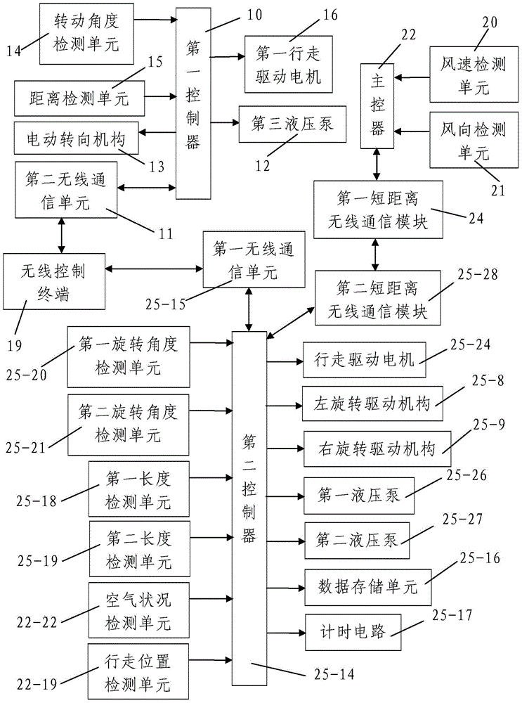
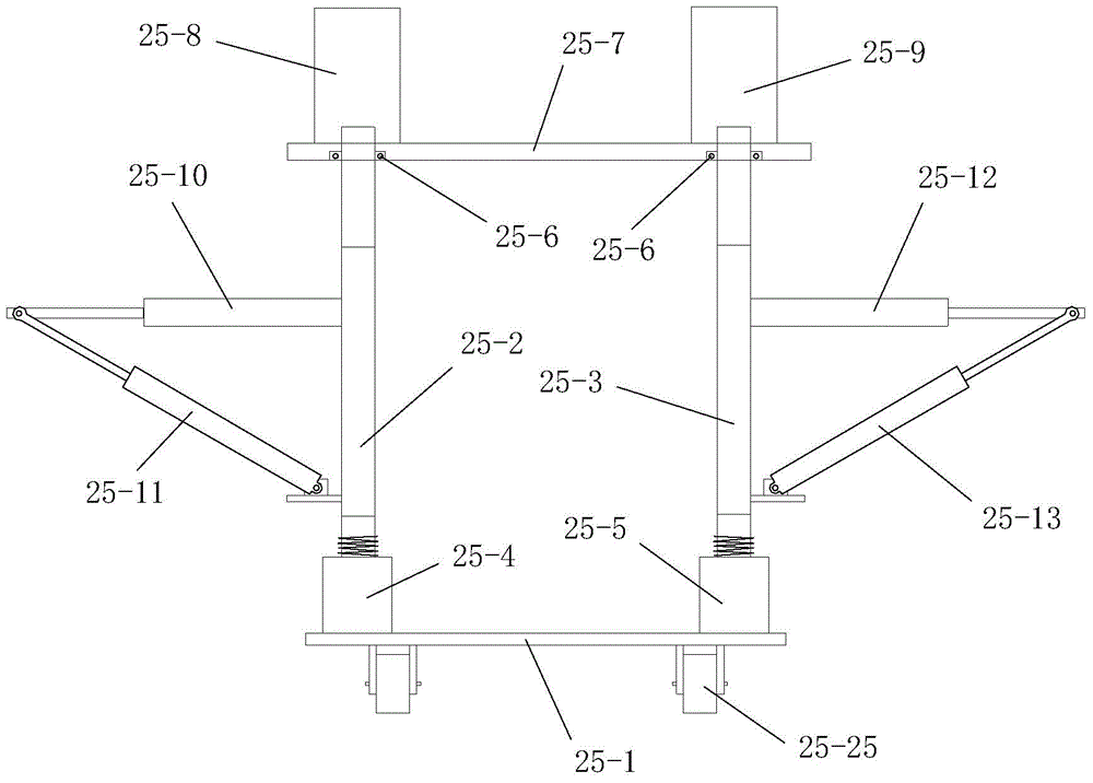
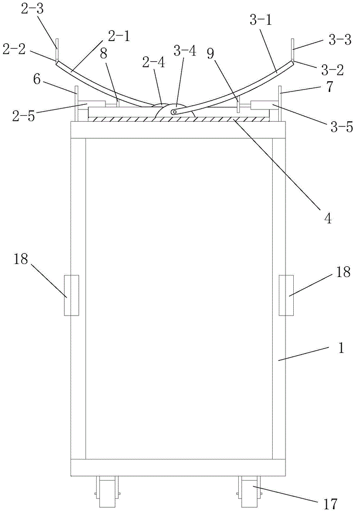
[0059] Such as figure 1 , figure 2 , image 3 and Figure 4 As shown, the present invention includes a wireless control terminal 19 carried by tunnel ventilation monitoring personnel, a ventilation state monitoring robot that can move back and forth in the tunnel hole under construction, a sensor mounting frame installed on the inner side wall of the tunnel hole under construction, The air supply state detection device for real-time detection of the air supply state of the flexible air duct in the tunnel under construction and the automatic adjustment vehicle for the diameter and direction of the air duct opening and direction in the tunnel under construction, the air supply state detection The device is installed on the sensor installation frame, and the sensor installation frame is located at the front side of the air supply port of the flexible air duct. The ventilation state monitoring robot communicates with the wireless control terminal 19 and the air supply state de...


PUM


Abstract

The invention discloses a tunnel in-tunnel ventilation regulating and control device based on a wireless control terminal. The tunnel in-tunnel ventilation regulating and control device comprises the wireless control terminal, a ventilation state monitoring robot, a sensor installing frame, an air supply state detection device and an air pipe opening caliber and facing direction automatic regulating vehicle, wherein the wireless control terminal is carried about by tunnel ventilation monitoring personnel; the ventilation state monitoring robot can forwards and backwards move in a constructed tunnel; the sensor installing frame is arranged on the inner side wall of the constructed tunnel; the air pipe opening caliber and facing direction automatic regulating vehicle can forwards and backwards move in the constructed tunnel; the ventilation state monitoring robot and the wireless control terminal are communicated in a wireless communication mode; and the air supply state detection device, the wireless control terminal and the air pipe opening caliber and facing direction automatic regulating vehicle are communicated in the wireless communication mode. The tunnel in-tunnel ventilation regulating and control device has the advantages that the structure is simple; the design is reasonable; the operation is simple and convenient; the use effect is good; after the blasting is completed, the face blasting fume and harmful gas distribution condition and the air supply condition of a tunnel ventilation pipeline can be monitored after the blasting completion; and the pipe opening size of a flexible air pipe and the pipe opening facing direction can be simply and conveniently regulated.

Description

technical field [0001] The invention belongs to the technical field of tunnel ventilation construction, and in particular relates to a ventilation control device in a tunnel based on a wireless control terminal. Background technique [0002] At present, the tunnel construction ventilation at home and abroad mostly adopts the pipeline press-in ventilation method, and an axial flow fan is installed outside the tunnel entrance. The fresh air is sent to the tunnel excavation face, and the dirty air in the tunnel is expelled out of the tunnel along the excavated tunnel body under the squeeze of the fresh air sent into the tunnel. When the tunnel is long, multiple axial flow fans are used in parallel and in series to increase the air volume and air supply distance. In the actual construction process, after the blasting is completed, the concentration of blast smoke and harmful gases produced by blasting and transportation in the cave is relatively large. Next, adjust the wind sp...

Claims


Application Information

Patent Timeline
Patent Type & Authority Applications(China)
IPC IPC(8): E21F1/00E21F17/18
Inventor 介艳良
Owner XIAN KUOLI MACHANICAL & ELECTRICAL TECH
Learn More