Transmission structure of high-temperature atmosphere rotary furnace
A transmission structure and rotary furnace technology, applied in the direction of rotary drum furnaces, furnaces, furnace types, etc., can solve the problems of slow material conveying speed, large heat loss, and large load of driving motors
Inactive Publication Date: 2016-06-08
SUZHOU HUIKE EQUIP CO LTD
View PDF6 Cites 0 Cited by
- Summary
- Abstract
- Description
- Claims
- Application Information
AI Technical Summary
Problems solved by technology
[0002] The existing powder is heated and transported through a pusher kiln or a roller kiln, and the material is mixed with the heat emitted by the hot air burned in the kiln for heating. During the conveying process, the material is not heated uniformly, and The heat loss is relatively large, so that the heating of the material requires a huge amount of energy, and because the material is heated unevenly, the heating time of the material in the kiln chamber is long, which makes the work efficiency of the entire material heating and transportation low, delays the entire production process, and makes the production line The production efficiency is low; in addition, in the existing rotary furnace, the entire heating furnace body rotates, so that the load on the driving motor is large, and the driving efficiency is low, and the two ends of the heating furnace tube are respectively supported by the bearing structure, and the cost of the bearing structure is high. Moreover, in the actual furnace tube rotation process, the material is only conveyed by the rotation of the furnace tube, so that the material conveying speed is relatively slow, and the best feeding efficiency of the entire rotary furnace cannot be ensured.
Method used
View moreImage
Smart ImageViewing Examples
Examples
specific Embodiment 2
[0021] Specific embodiment two: the front end of the unpowered roller group at the front end can also be set as an output gear. At this time, the output end of the drive motor is connected to the output gear. output gear.
Login to View More PUM
 Abstract
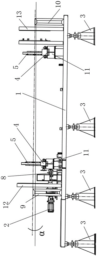
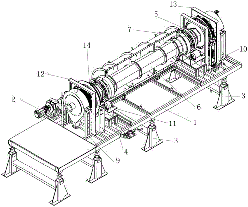
The invention provides a transmission structure of a high-temperature atmosphere rotary furnace, by means of the transmission structure, feeding efficiency of the whole rotary furnace can be high, the whole structure is simple, and conveying efficiency is high. The transmission structure comprises a bottom plate, the bottom plate is provided with a drive motor, the bottom plate is supported by a plurality of ascending / descending platforms with adjustable height in the material conveying direction, the bottom plate is downwards inclined in the material conveying direction, the two ends of the bottom plate are provided with unpowered roller groups in the length direction respectively, each unpowered roller group is composed of rollers on the two sides, each unpowered roller group is configured with a rolling ring structure, the center of each rolling ring structure is provided with a penetrating hole matched with the cross section of a furnace pipe, the rolling ring structure is arranged at the corresponding end of the furnace pipe in a sleeved mode, the outer annular face of the lower portion of each rolling ring structure is supported on the rollers on the two sides, the front end of the unpowered roller group at the front end is provided with an output chain wheel, the output end of the drive motor is connected with an output chain wheel, the position, corresponding to the output chain wheel, of the furnace tube is sleeved with the input chain wheel, and the output chain wheel and the input chain wheel are connected through a chain.
Description
technical field [0001] The invention relates to the technical field of material conveying and heating, in particular to a transmission structure of a high-temperature atmosphere rotary furnace. Background technique [0002] The existing powder is heated and transported through a pusher kiln or a roller kiln, and the material is mixed with the heat emitted by the hot air burned in the kiln for heating. During the conveying process, the material is not heated uniformly, and The heat loss is relatively large, so that the heating of the material requires a huge amount of energy, and because the material is heated unevenly, the heating time of the material in the kiln chamber is long, which makes the work efficiency of the entire material heating and transportation low, delays the entire production process, and makes the production line The production efficiency is low; in addition, in the existing rotary furnace, the entire heating furnace body rotates, so that the load on the d...
Claims
Login to View More Application Information
Patent Timeline
 Patent Type & Authority Applications(China)
IPC IPC(8): F27B7/26F27B7/00F27B7/32
CPCF27B7/26F27B7/00F27B7/3205
Inventor 陈龙豪陈斌张文俊
Owner SUZHOU HUIKE EQUIP CO LTD
Features
- R&D
- Intellectual Property
- Life Sciences
- Materials
- Tech Scout
- Unparalleled Data Quality
- Higher Quality Content
- 60% Fewer Hallucinations
Learn More Browse by: Latest US Patents, China's latest patents, Technical Efficacy Thesaurus, Application Domain, Technology Topic, Popular Technical Reports.
© 2025 PatSnap. All rights reserved.Legal|Privacy policy|Modern Slavery Act Transparency Statement|Sitemap|About US| Contact US: help@patsnap.com


