
High-temperature extrusion molding machine

A molding machine, high temperature technology, applied in the field of plastic processing, can solve the problems of poor heating effect, long mixing time, uneven heating of barrel raw materials, etc., to achieve the effect of reducing mixing time, uniform heating, and improving extrusion efficiency

Active Publication Date: 2020-03-31
天长市诚信塑业有限公司
View PDF10 Cites 1 Cited by
  • Summary
  • Abstract
  • Description
  • Claims
  • Application Information

AI Technical Summary

Problems solved by technology

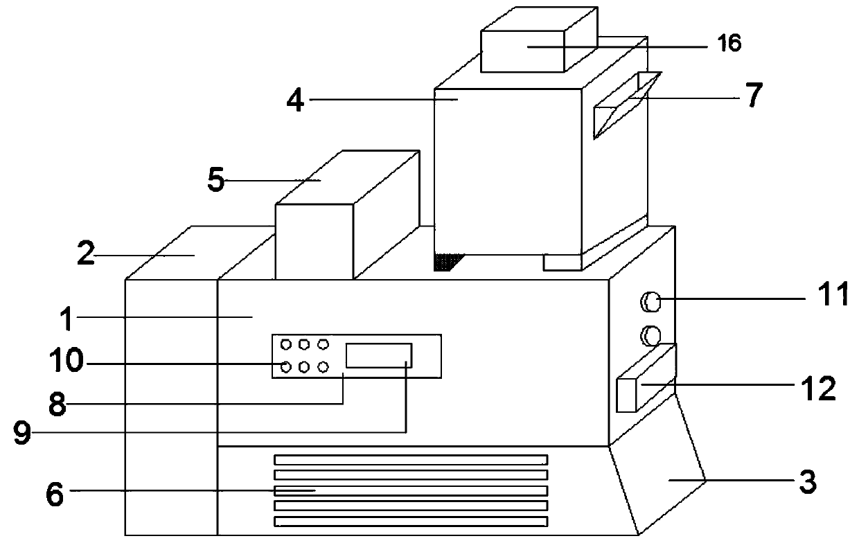
[0006] The purpose of the present invention is to solve the problems of poor heating effect of the three-screw extruder in the prior art, uneven heating of raw materials inside the barrel, and long mixing time, and proposes a high-temperature extrusion molding machine

Method used


Image

  • High-temperature extrusion molding machine
  • High-temperature extrusion molding machine
  • High-temperature extrusion molding machine

Examples


Embodiment 1

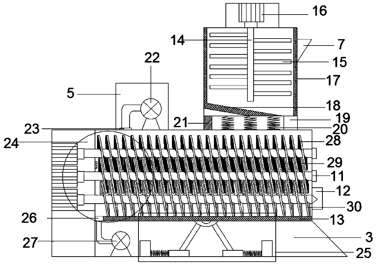
[0031] refer to Figure 1-2 and Figure 5-6, a high-temperature extrusion molding machine, comprising an extrusion box 1, a power box 2 arranged on one side of the extrusion box 1, a feed box 4 at the top of the extrusion box 1 and a base 3 at the bottom of the extrusion box 1, said Stirring motor 16 is arranged on the top of feeding box 4, and stirring shaft 14 is arranged inside feeding box 4, and described stirring shaft 14 is connected with output shaft of stirring motor 16, and described stirring shaft 14 both sides are staggered to be provided with stirring blade 15, The upper end of one side of the feed box 4 is provided with a feed inlet 7, and a layer of electric heating layer 17 is arranged on the inner side wall of the feed box 4, and a feed inlet 19 is arranged on one side of the bottom of the feed box 4, and the feed inlet 19 is connected to the The extrusion box 1 is connected, and the other side of the bottom of the feeding box 4 is provided with a support plat...

Embodiment 2

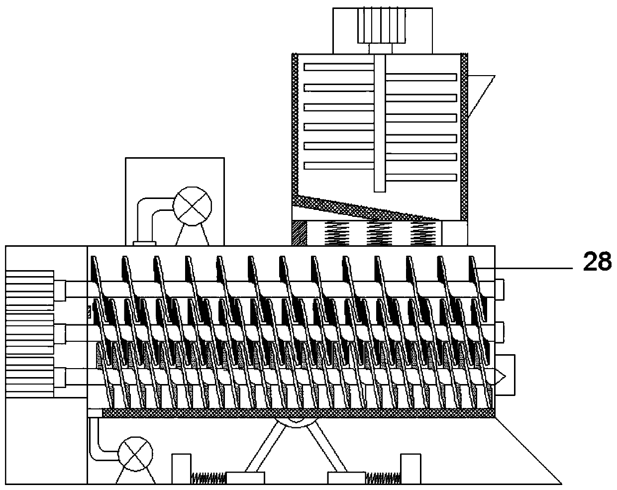
[0038] Such as image 3 As shown, this embodiment is basically the same as Embodiment 1. Preferably, the number of helical blades of the first helical blade 28 is half of that of the second helical blade 29, and the first helical blades 28 and the second helical blades 29 are arranged alternately. . It can effectively make the masterbatch fall into the second screw blade 29 and the third screw blade 30 below as soon as possible, so as to speed up the extrusion efficiency, reduce the use of heating wires, and save energy.

Embodiment 3

[0040] Such as Figure 4 As shown, this embodiment is basically the same as Embodiment 1. Preferably, the bottom end of the power box 2 is provided with a No. 1 motor 33, and the third rotating shaft 31 and the first rotating shaft 40 extend through the extrusion box 1 into the power box 2. , is rotationally connected with the side wall of the power box 2, the output shaft of the No. 1 motor 33 is rotationally connected with the third rotating shaft 31 and the first rotating shaft 40 through a rotating belt 34, and the second rotating shaft 39 is connected with the No. 2 motor 32 in the power box 2 The output shaft is fixedly connected, and the No. 2 motor 32 and the No. 1 motor 33 are electrically connected with the control button 10 . The third rotating shaft 31 and the first rotating shaft 40 can be rotated synchronously, and the rotation speed of the second rotating shaft 39 and the third rotating shaft 31 and the first rotating shaft 40 can be adjusted conveniently, so as...


PUM


Abstract

The invention discloses a high-temperature extrusion molding machine, and relates to the technical field of plastic processing. The high-temperature extrusion molding machine comprises an extrusion molding box, a power box, a feeding box and a base, wherein a stirring shaft is arranged in the feeding box; an electric heating layer is arranged on the side wall of the interior of the feeding box; anextrusion molding mechanism is arranged in the extrusion molding box; the extrusion molding mechanism comprises a first spiral blade, a second spiral blade and a third spiral blade which are staggered with one another; one end of a first rotating shaft, one end of a second rotating shaft and one end of the third rotating shaft penetrate through the side wall of the extrusion molding box and are connected with an output shaft of a rotating motor in the power box; and electric heating wires are arranged on the first spiral blade and the second spiral blade. According to the high-temperature extrusion molding machine, the defects in the prior art are overcome, the design is reasonable, the use is convenient, the primary premixing of the master batch is carried out, then spiral extrusion is carried out, meanwhile, the extrusion efficiency is effectively improved by using a spiral blade heating mode, the heat waste is prevented, and the labor loss is reduced.

Description

technical field [0001] The invention relates to the technical field of plastic processing, in particular to a high-temperature extrusion molding machine. Background technique [0002] The extruder is an important plastic machine. The production and manufacture of most plastic products can be realized by extrusion molding. Generally, the extruder uses a screw with a specific shape to rotate in a heated barrel to extrude plastic. forming. [0003] When the extruder is in use, most of the plastic masterbatch is directly added to the barrel, heated by the heating element inside the barrel, and then extruded through the spiral blade on the screw extrusion rod. In the process of stirring, in order to make the masterbatch mix More uniform, twin-screw or three-screw extruder is often used for extrusion. Among them, the three-screw extruder has the advantages of strong plasticizing ability, good mixing effect, and better self-cleaning performance of the twin-screw plastic extruder. ...

Claims


Application Information

Patent Timeline
Patent Type & Authority Applications(China)
IPC IPC(8): B29C48/36B29C48/40B29C48/793B29C48/80
CPCB29C48/36B29C48/40B29C48/793B29C48/802
Inventor 俞东铭俞俊刚
Owner 天长市诚信塑业有限公司
Learn More