Analysis method for testing fatigue life of components based on vibration signals
A technology of fatigue analysis and fatigue life, applied in vibration testing, testing of machines/structural components, measuring devices, etc., can solve problems such as sudden failures, and achieve the effect of facilitating fatigue life prediction and analysis
Inactive Publication Date: 2016-06-08
QINGDAO R & D INST XIAN JIAOTONG UNIV
View PDF7 Cites 41 Cited by
- Summary
- Abstract
- Description
- Claims
- Application Information
AI Technical Summary
Problems solved by technology
If the structure under the action of alternating load is only checked according to t
Method used
View moreImage
Smart ImageViewing Examples
Examples
 PUM
 Abstract
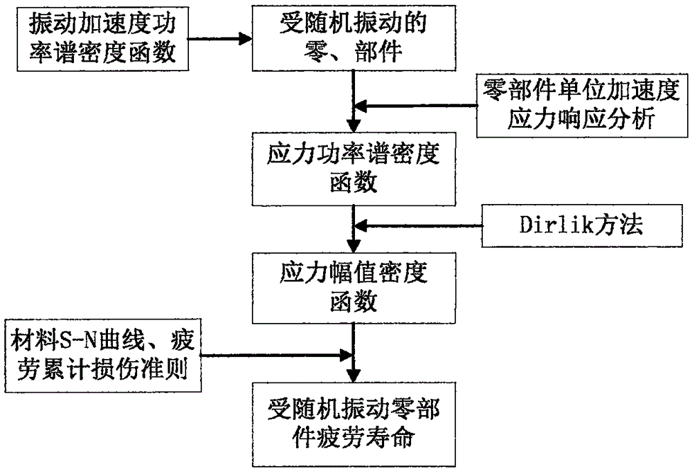
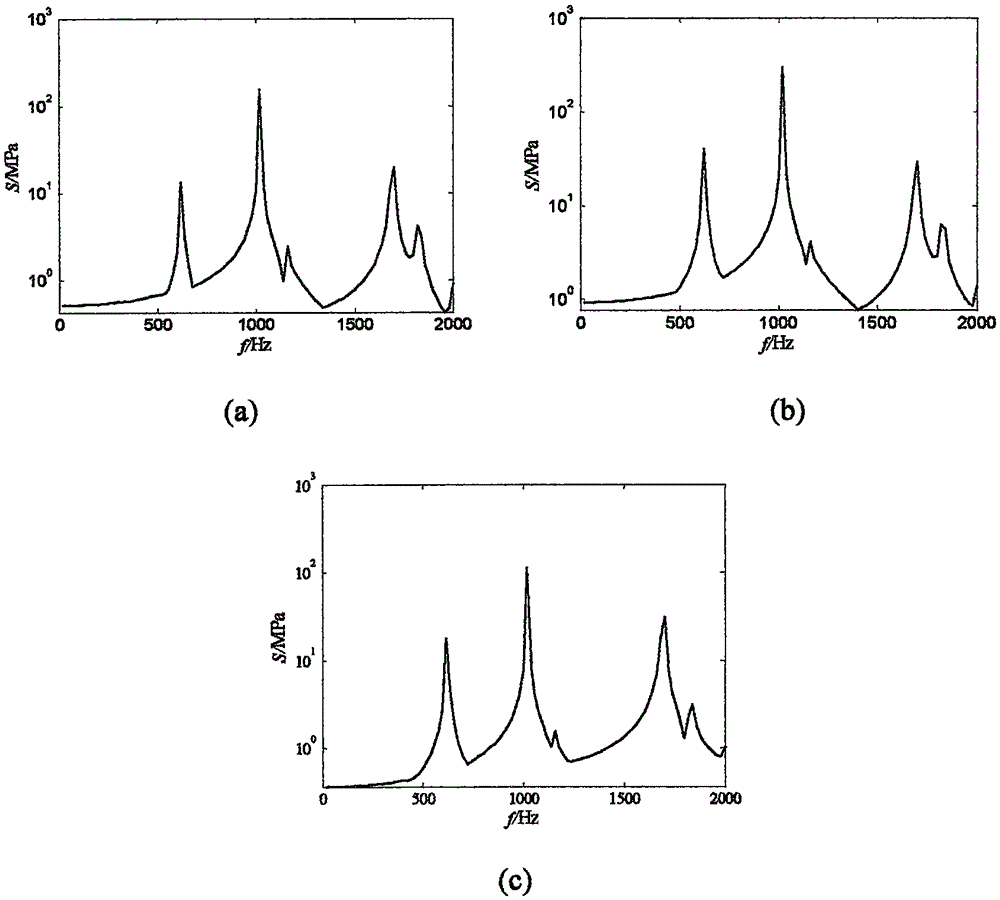
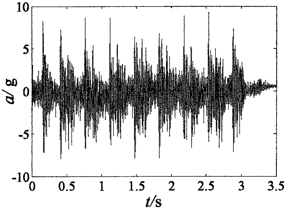
The invention discloses an analysis method for testing the fatigue life of components based on vibration signals. The analysis method comprises the following steps that (1) a power spectral density function Ga (f) of working field random vibration acceleration load of the components is calculated according to the acquired random vibration acceleration load time domain signals xa(t) of the components; (2) a stress frequency response function HS(f) under the unit acceleration (1g) load of the components is solved by utilizing finite element harmonic response analysis; and a stress power spectral density function of the structure is acquired through combination of (1) based on the working field random vibration acceleration load of the components; and (3) a stress load distribution probability density function of the components is solved according to a Dirlik method by utilizing the working field random vibration acceleration load power spectral density of the components, and a random vibration fatigue analysis load spectrum is established to perform random vibration fatigue analysis on the components. The problem that stress amplitude information of the components working in the complex working conditions is difficult to obtain directly and fatigue life pre-estimation cannot be performed can be solved.
Description
technical field [0001] The invention relates to the fatigue life analysis technology of parts in service, in particular to an analysis method for testing the fatigue life of parts based on vibration signals. Background technique [0002] The problem of structural fatigue failure has a long history. As early as the middle of the 19th century, with the invention of the steam engine and the development of railway construction, it was found that the train wheel structure can be damaged by alternating stress when the load is much smaller than its static strength limit load. This phenomenon The structural fatigue problem which is different from the static strength failure of the structure is proposed and developed. A large number of statistical data show that 50% to 90% of the fracture accidents of mechanical parts are caused by fatigue damage. The purpose of fatigue analysis is to predict the fatigue life of the structure, and to study the dynamic performance of the structure th...
Claims
Login to View More Application Information
Patent Timeline
 IPC IPC(8): G01M7/02
CPCG01M7/025
Inventor 苗慧慧陈雪峰张欢男张兴武
Owner QINGDAO R & D INST XIAN JIAOTONG UNIV
Features
- R&D
- Intellectual Property
- Life Sciences
- Materials
- Tech Scout
- Unparalleled Data Quality
- Higher Quality Content
- 60% Fewer Hallucinations
Learn More Browse by: Latest US Patents, China's latest patents, Technical Efficacy Thesaurus, Application Domain, Technology Topic, Popular Technical Reports.
© 2025 PatSnap. All rights reserved.Legal|Privacy policy|Modern Slavery Act Transparency Statement|Sitemap|About US| Contact US: help@patsnap.com


