Glue dipping method for dry capacitive high voltage bushing core

A high-voltage bushing and capacitive technology, which is applied in the direction of circuits, insulators, electrical components, etc., can solve the problems of low product pass rate and difficult to eliminate air bubbles, and achieve high product pass rate, increase pass rate, and reduce production costs. Effect

Active Publication Date: 2017-05-03
石家庄市发运电气有限公司
View PDF6 Cites 0 Cited by
  • Summary
  • Abstract
  • Description
  • Claims
  • Application Information

AI Technical Summary

Problems solved by technology

[0005] The purpose of the present invention is to provide a method for impregnating the core body of a dry capacitor type high voltage bushing to solve the problem that the air bubbles are difficult to be eliminated during the dipping operation of the core body of a dry capacitor type high voltage bushing, resulting in a low product qualification rate.

Method used


Image

  • Glue dipping method for dry capacitive high voltage bushing core

Examples


Embodiment 1

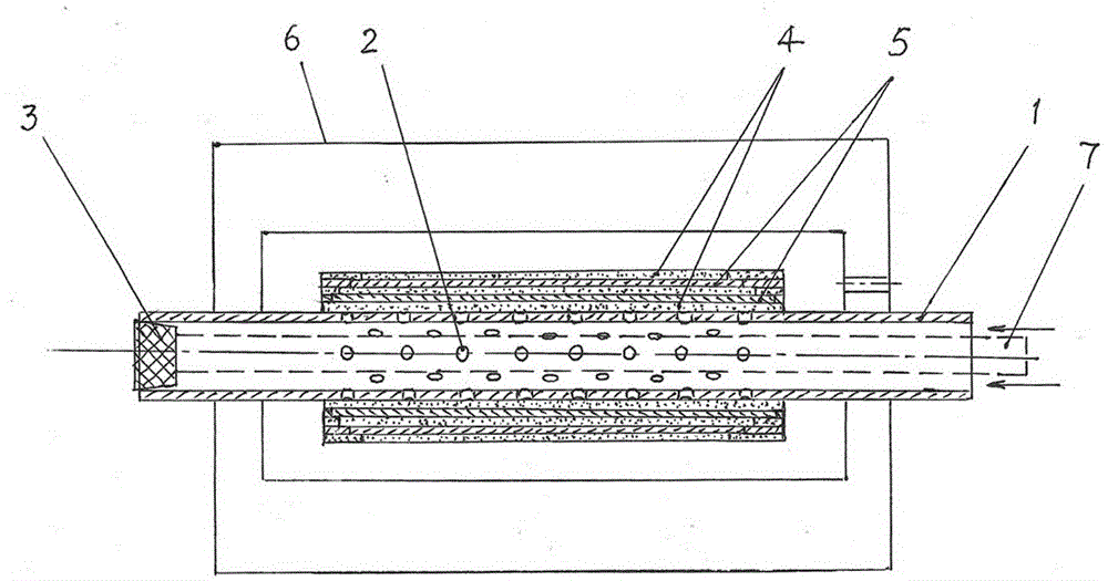
[0025] Such as figure 1 As shown, the dipping method of the dry capacitor type high voltage bushing core of the present invention comprises the following steps:

[0026] 1. A plurality of distributed through-holes 2 are opened on the tube wall within the range of the capacitive screen on the conductive tube 1, so that the tube section forms a mesh tube section.

[0027] 2. Plug one end of the conductive tube 1 with a plug 3 to form a closed end. The closed end of the conductive tube 1 should be able to withstand more than 2 atmospheric pressures.

[0028] 3. Wrap the outer circumference of the conductive tube 1 with an insulating material to form an insulating layer 4 covering the conductive tube, and then wrap the outer circumference of the insulating layer 4 with a conductive material to form a capacitive screen 5 that covers the insulating layer. The outer circumference of 5 is wound with insulating material to form an insulating layer covering the capacitive screen. Afte...

Embodiment 2

[0034] Such as figure 1 As shown, the dipping method of the dry capacitor type high voltage bushing core of the present invention comprises the following steps:

[0035] 1. A plurality of distributed through-holes 2 are opened on the tube wall within the range of the capacitive screen on the conductive tube 1, so that the tube section forms a mesh tube section.

[0036] 2. Insert an inner tube 7 into the conductive tube 1. The length of the inner tube 7 can be longer than the length of the conductive tube 1. There is a sufficient glue gap between the outer wall of the inner tube 7 and the inner wall of the conductive tube 1.

[0037]3. Close the same side (left end) of the conductive tube 1 and the inner tube 7 (the dotted line in the figure), and the closed end of the conductive tube 1 should be able to withstand more than 3 atmospheric pressures. In addition, the right end of the inner tube 7 should protrude from the open end of the conductive tube 1 .

[0038] 4. Wrap the...


PUM


Abstract

The invention relates to an impregnation method for a dry capacitance type high-voltage bushing core. The impregnation method comprises steps as follows: distributed through holes are formed in the wall of a conductive tube, one end of the conductive tube is closed, the conductive tube is wound with an insulating layer, then the insulating layer is wound with a capacitive screen, and alternate winding is performed until the specified layer number of the capacitive screens is reached; a prepared bushing core blank body is arranged in an airtight pouring die, glue with pressure is introduced through an open end of the conductive tube, is enabled to permeate layer by layer to an external wrapping layer through the through holes in the conductive tube and is gradually diffused to all insulating layers and capacitive screens, and an impregnation process of the bushing core is finished after heating and curing forming. According to the impregnation method, diffusion and permeation of the glue can be formed from inside to outside, retention of bubbles is avoided, the qualified rate of products can be increased more than 3 times after impregnation, heating and curing, the impregnation quality is also greatly improved, further, the production cost is reduced, and the economic benefit of a production enterprise can be greatly increased.

Description

technical field [0001] The invention relates to a manufacturing method of a high-voltage power transmission and transformation component, in particular to a glue-dipping method for a core body of a dry capacitor type high-voltage bushing. Background technique [0002] In order to obtain a relatively uniform electric field distribution, the main insulation structure of the bushing core of the dry capacitive high voltage bushing is generally made in two ways: the first way is the glue (resin) impregnated paper capacitive bushing , the main insulation structure of the casing core is to wrap a certain thickness (2-5mm) of crepe paper along the outer circumference of the conductive tube in a concentric circle, use the crepe paper as the support layer, and then fold and wind the concentric conductive foil to make it Capacitive screen, according to the different voltage levels applicable to high-voltage bushings, several layers of crepe paper and capacitive screens are alternately ...

Claims


Application Information

Patent Timeline
Patent Type & Authority Patents(China)
IPC IPC(8): H01B19/02
CPCH01B19/02
Inventor 孟繁恒
Owner 石家庄市发运电气有限公司
Why Eureka
Try Eureka