A spacecraft deployment mechanism

A technology for deploying mechanisms and spacecraft, applied in space shuttles, folding antennas, etc., can solve the problems of large impact, small load range, and uncontrolled deployment, and achieve the effects of good support rigidity, large adaptability, and reduced additional force

Active Publication Date: 2012-02-22
BEIJING INST OF SPACECRAFT SYST ENG
View PDF0 Cites 0 Cited by
  • Summary
  • Abstract
  • Description
  • Claims
  • Application Information

AI Technical Summary

Problems solved by technology

[0007] Aiming at the shortcomings of the passive deployment mechanism such as uncontrolled deployment process, large deployment impact and small applicable load range, the present invention proposes an active spacecraft deployment mechanism, which can better overcome the above problems

Method used


Image

  • A spacecraft deployment mechanism
  • A spacecraft deployment mechanism
  • A spacecraft deployment mechanism

Examples


Embodiment Construction

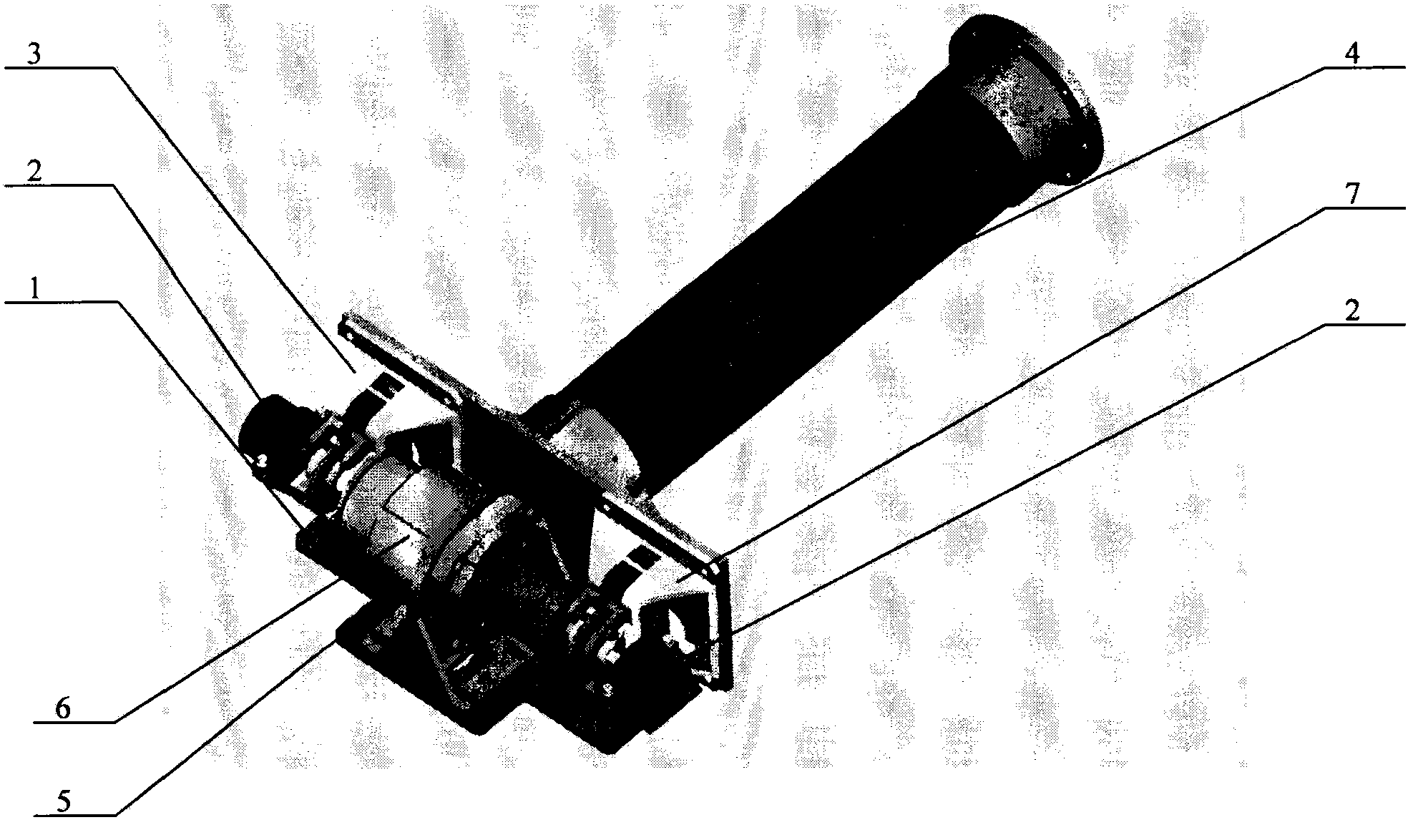
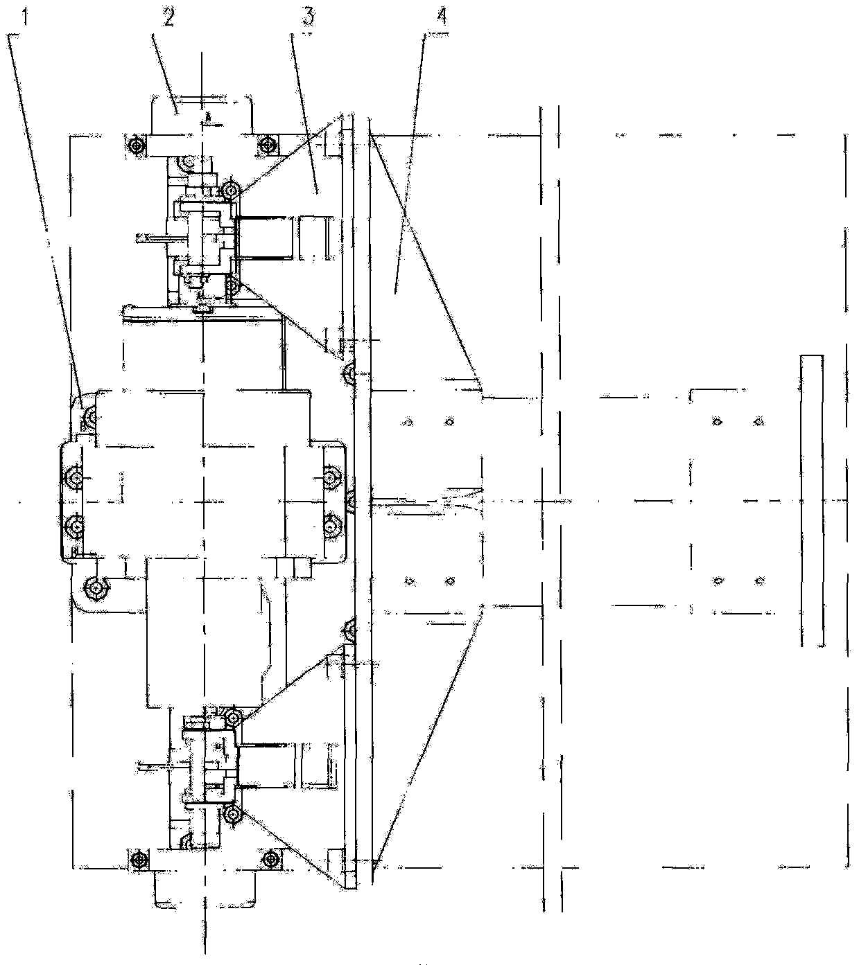
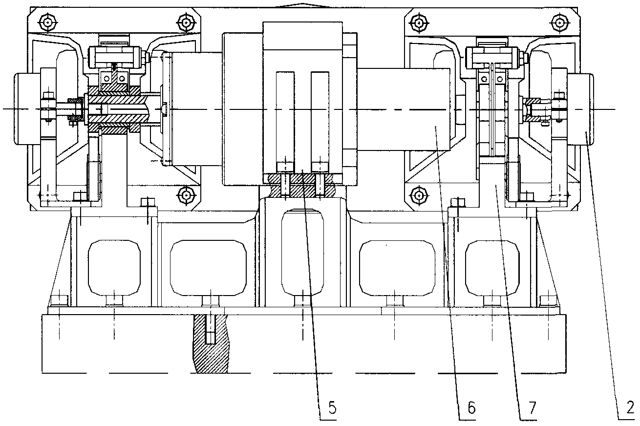
[0034] figure 1 It is a three-dimensional configuration diagram of the spacecraft deployment mechanism of the present invention, and Fig. 2 is a two-dimensional configuration diagram of the spacecraft deployment mechanism of the present invention, wherein Figure 2a for top view, Figure 2b for side view. The deployment mechanism of the present invention includes an active drive assembly 6 , a first locking assembly 7 , a second locking assembly 3 , a base 1 , a first sensor assembly 8 , a second sensor assembly 2 , a connecting bracket 4 and a platen bracket 5 .

[0035]The active driving assembly 6 is placed between the first locking assembly 7 and the second locking assembly 3, the output shaft 22 of the active driving assembly 6 is connected with the second locking assembly 3, and the first locking assembly 7 and the second locking assembly 3 pass through The connecting brackets 4 are connected together. When working, the active drive assembly 6 drives the locking assem...


PUM


Abstract

The spacecraft deployment mechanism of the present invention adopts a combined form of an active driving assembly and a mechanical locking mechanism. The mechanical locking mechanism includes a first locking assembly and a second locking assembly, and the first locking assembly and the second locking assembly are distributed between the two active driving assemblies. end, the active drive assembly is connected to the second locking assembly, the second locking assembly is connected to the first locking assembly through the connecting bracket, and the active driving assembly, the first locking assembly and the second locking assembly are connected together through the base; when working, The active driving component drives the second locking component to move, and the second locking component drives the first locking component to move through the connecting bracket. After being unfolded in place, the first locking component and the second locking component respectively complete locking. The deployment mechanism also includes a sensor assembly and a micro switch. The invention has a simple and reliable structure, has little disturbance and influence on the spacecraft, can adapt to load requirements in a relatively large range, and can meet the requirements of high precision and high rigidity under space conditions.

Description

technical field [0001] The invention relates to a spacecraft deployment mechanism, in particular to a spacecraft deployment mechanism using an active drive assembly and a mechanical locking mechanism. Background technique [0002] The spacecraft deployment mechanism is a mechanism that unfolds or stretches the primary and secondary structures, antennas, solar wings and other components of the spacecraft to a predetermined position or shape. The spacecraft deployment mechanism is a mechanism field that gradually develops from simple to complex with the birth, development, and maturity of satellites. Early satellites deployed rod antennas by spinning power; after the appearance of the unfolded solar wing, the folding antenna deployment mechanism has become the most typical deployment mechanism that has been used until now; with the gradual increase in the volume and weight of spacecraft, gradually produced Truss antenna deployment mechanism, inflatable antenna deployment mech...

Claims


Application Information

Patent Timeline
Patent Type & Authority Patents(China)
IPC IPC(8): H01Q1/08B64G1/14
Inventor 胡成威孙京金俨刘宾曹鹏夏祥东
Owner BEIJING INST OF SPACECRAFT SYST ENG
Why Eureka
Try Eureka