Powered mobility device with tilt mechanism having multiple pivots

A mobile device and pivot technology, which is applied in the field of electric mobile devices, can solve the problems of inapplicability and the inability to precisely control the driving of wheelchairs, etc.

Active Publication Date: 2016-06-15
OGO TECH LTD
View PDF8 Cites 4 Cited by
  • Summary
  • Abstract
  • Description
  • Claims
  • Application Information

AI Technical Summary

Problems solved by technology

Current wheelchairs are controlled by the position of the user's center of gravity, however these wheelchairs cannot

Method used


Image

  • Powered mobility device with tilt mechanism having multiple pivots
  • Powered mobility device with tilt mechanism having multiple pivots
  • Powered mobility device with tilt mechanism having multiple pivots

Examples


Embodiment Construction

[0039] The following description relates to a preferred embodiment of the invention, a motorized wheelchair that can be steered with or without the use of both hands. The invention is not limited to the described preferred embodiments, since the preferred embodiments are presented as illustrations of the invention only. Obvious variations and modifications are possible without departing from the scope of the present invention.

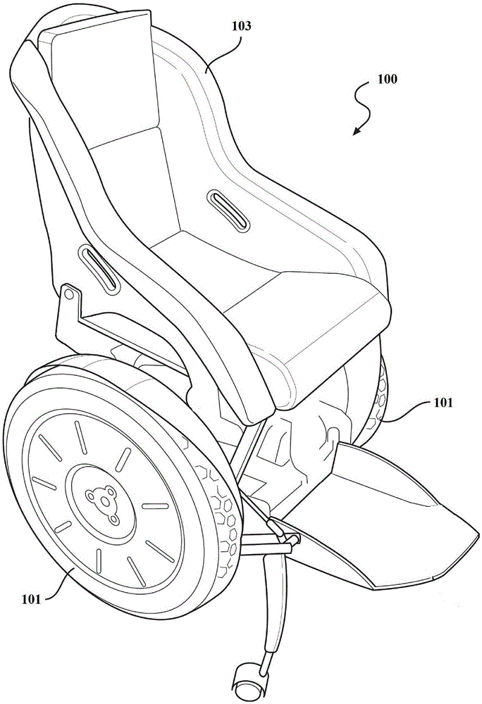
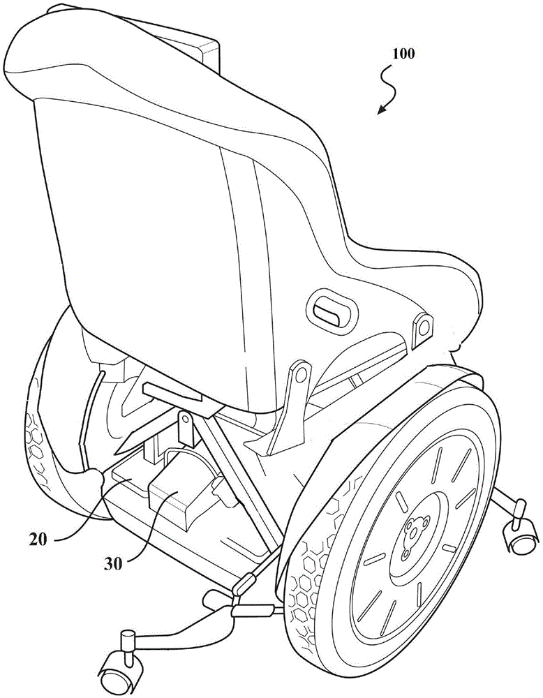
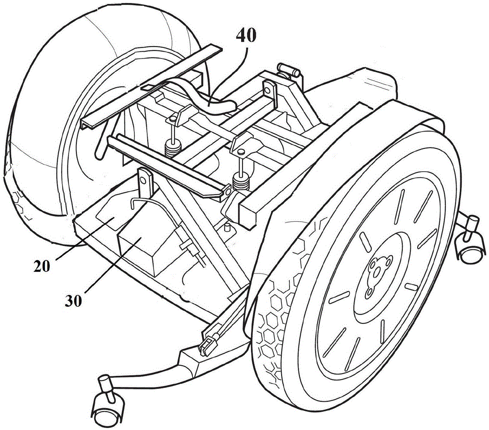
[0040] Figure 1 to Figure 5 The mobility device shown is a preferred embodiment of a wheelchair.

[0041] Figure 1 to Figure 3 different views of the wheelchair 100 are shown, Figure 4 and Figure 5 The multi-pivot layout of wheelchair 100 is shown in detail.

[0042] The wheelchair 100 is an electric wheelchair 100 powered by a battery, however other known modes of powering the wheelchair 100 are still contemplated.

[0043] The wheelchair 100 can be used on and off road conditions. The wheelchair 100 can be operated with or without the use ...


PUM


Abstract

The invention relates to a powered wheelchair 100 with a tilt mechanism provided with multiple pivots which is able to be steered with or without the use of hands. The wheelchair 100 is provided with two spaced drive wheels 101, and each drive wheel is mounted on a separate drive shaft 104 without impact of the other drive wheel. A drive controller is coupled to the drive shaft 104, and the drive controller is located inside the base 102, pivotally connected to the drive shaft 104. A user moves the body gravity center or moves its direction such that the wheelchair seat 103 mounted on the tilt mechanism leans forward, backward, left and right. The tilt mechanism is equipped with a first grade pivot P1, a second grade P2 and a third grade pivot P3. The first grade pivot P1 makes a base 102 be pivotally connected to the drive shaft 104.The second grade pivot P2 is mounted on and adjacent to the base 102. Two ends of the drive rod 105 are pivotally connected to the base 102. The tilt mechanism and the drive controller are connected to the gravity center movement sensor to control the movement and advancing direction of the wheelchair 100. The first grade pivot P1 and the second grade pivot P2 make the wheelchair seat 103 move in the direction forward or backward(103F,103B) relatively to the drive wheels 101. The movement can be sensed by the gravity center movement sensor, and then the drive controller is actuated to transfer the drive force to one or two of the drive wheels, so that the wheelchair 100 is moved in accordance with the direction has been perceived, for example, forward or backward. The second grade pivot P2 can enlarge the offset of the user gravity center movement, thereby increasing the the control of the wheelchair seat 103 leaning forward or backward(103F,103B) with respect to the dirve shaft. Only the first grade pivot P1 is unable to make the drive shaft 104 operate. The third grade pivot P3 is located above the second grade pivot P2 and under and adjacent to the wheelchair seat 103, so that the two ends of the drive rod 105 can be pivotally connected to the wheelchair seat. The third grade pivot P3 can make the wheelchair seat 104 lean to the left or the right(103R,103L) through the tilt mechanism. The gravity center movement sensor which senses left and right movements prompts the drive controller transmitting the driving force to one or two drive wheels to make the wheelchair 100 turn toward left or right.

Description

technical field [0001] The present invention relates to an electric moving device equipped with a multi-pivot roll mechanism, and more particularly to an electric wheelchair which can be controlled with or without the use of hands. Background technique [0002] A problem with existing mobility devices is that users cannot easily operate existing mobility devices such as wheelchairs, especially users with impaired limbs (arms and legs) or limited mobility. [0003] Most wheelchairs are not suitable for use on all types of surfaces. Wheelchairs do not travel well on soft surfaces such as lawns or undulating surfaces, i.e. wheelchairs cannot be used 'off-road'. Prior art wheelchairs can easily get stuck and require assistance to travel "off-highway". [0004] Electric wheelchairs generally require manual control to drive the wheelchair forward and backward, and / or control the wheelchair forward and backward through only a pivot mechanism. Current wheelchairs are controlled b...

Claims


Application Information

Patent Timeline
IPC IPC(8): A61G5/04A61G5/10
CPCA61G5/04A61G5/10A61G2203/10A61G2203/30B62J45/4151B62K3/00B62K11/007B62K2204/00
Inventor 哈尔索尔·凯文·托马斯
Owner OGO TECH LTD
Why Eureka
Try Eureka