horizontal reactor

A technology for horizontal reactors and reaction chambers, applied in chemical/physical/physical-chemical stationary reactors, detailed information, chemical instruments and methods of chemical/physical/physical-chemical reactors, etc. It can be fully utilized, affect the concentration distribution and temperature distribution, and affect the production capacity of the reactor, so as to shorten the production time, increase the reaction space, and prevent back-mixing.

Active Publication Date: 2018-05-25
XIANGTAN UNIV
View PDF3 Cites 0 Cited by
  • Summary
  • Abstract
  • Description
  • Claims
  • Application Information

AI Technical Summary

Problems solved by technology

However, during the working process of the multi-stage reactor, the liquid level in each reaction chamber needs to reach the highest position of the overflow plate, so that the material can overflow to the next reaction chamber through the overflow plate, that is, when the upper When the liquid level of the primary reaction chamber does not reach the highest position of the overflow plate, there is no reactant in the lower reaction chamber, so that the amount of reactant in the reaction chambers of each level is uneven, and the reaction chambers of each level are not fully utilized; and There is a certain distance between the top of the overflow plate and the top wall of the reactor, thereby limiting the amount of reactants in each reaction chamber and affecting the production capacity of the reactor
At the same time, when the liquid levels of the adjacent two-stage reaction chambers reach the highest position of the overflow plate, it is easy to produce the phenomenon of back-mixing of the materials in the next-stage reaction chamber, thereby affecting the concentration distribution and temperature distribution of the materials during the reaction process. , affecting product quality

Method used


Image

  • horizontal reactor
  • horizontal reactor
  • horizontal reactor

Examples


Embodiment 1

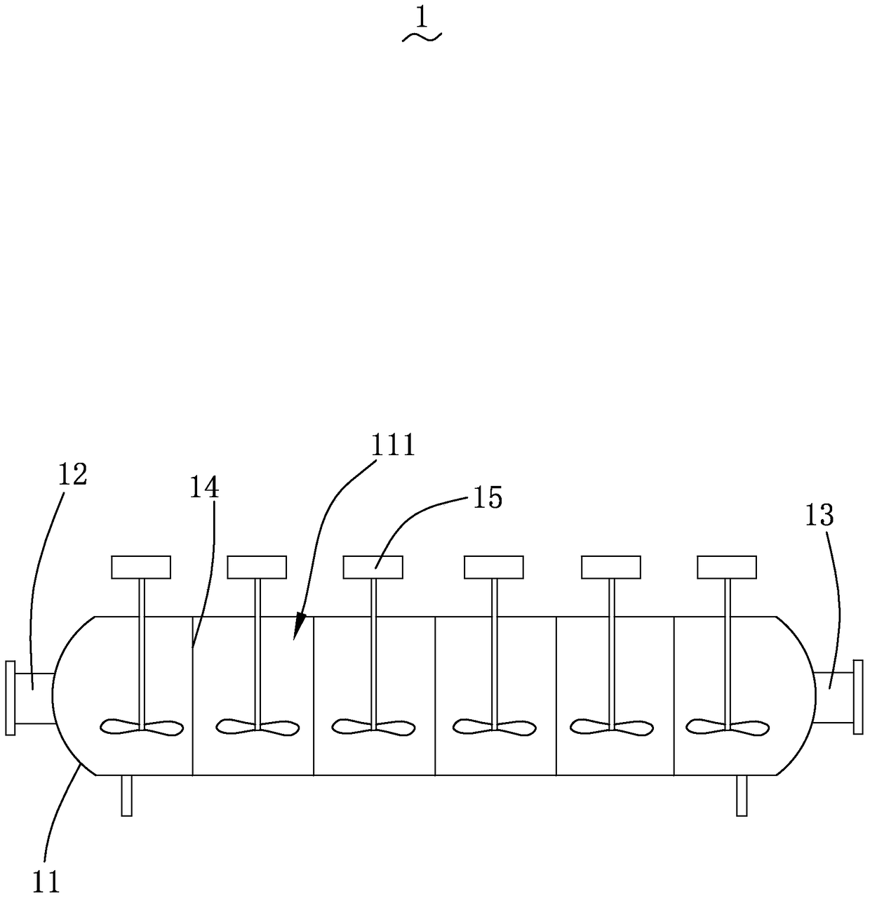
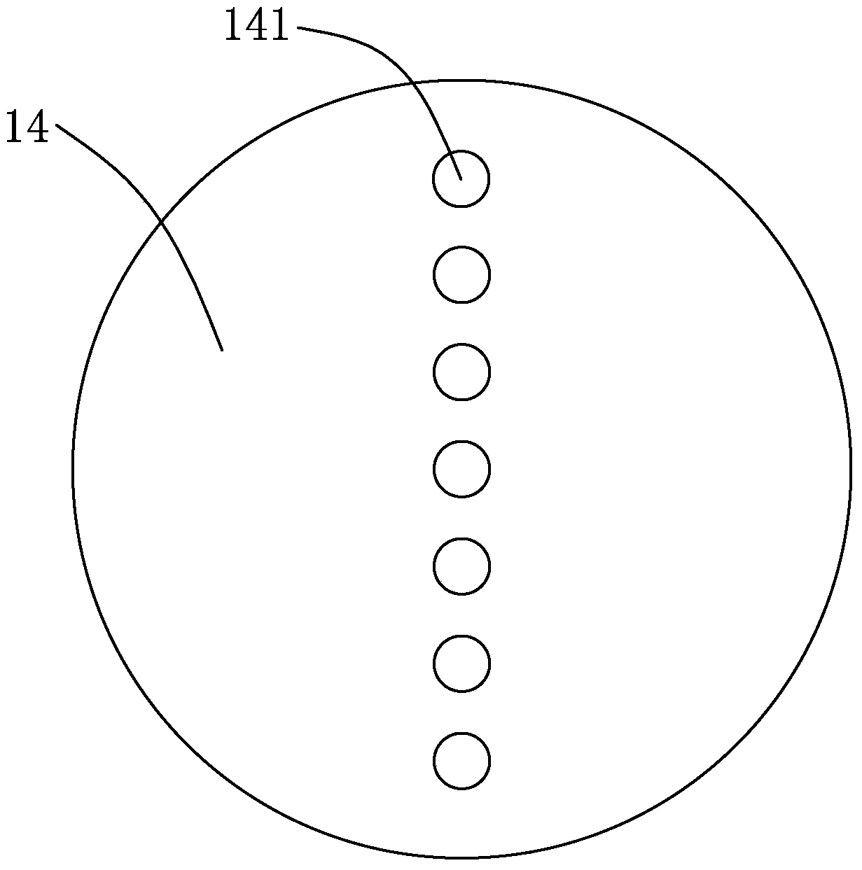
[0023] see figure 1 , is a schematic structural view of the horizontal reactor of the present invention. The horizontal reactor 1 includes a housing 11 with a receiving space (not labeled), a feed inlet 12 , a feed outlet 13 , a plurality of partitions 14 and a stirring device 15 . The feed port 12 and the discharge port 13 are located at both ends of the housing 11, the feed port 11 is used to transport the reaction material into the housing 11, and the discharge port 13 Used to output the reacted product. A plurality of partitions 14 are arranged at intervals in the housing space of the housing 11 perpendicular to the flow direction of the material along the material inlet 12 to the outlet 13 . The stirring device 15 is used to stir the materials so that the reactants can be mixed evenly and the reaction efficiency can be improved.

[0024] The number of the partitions 14 is 1-7. Correspondingly, the accommodation space of the housing 11 is divided to form 2-8 reaction ch...

Embodiment 2

[0034] The structure of the horizontal reactor in this embodiment is basically the same as that in Example 1, the difference lies in the distribution of the guide flow holes in the separator. The partition structure of this embodiment will be described in detail below.

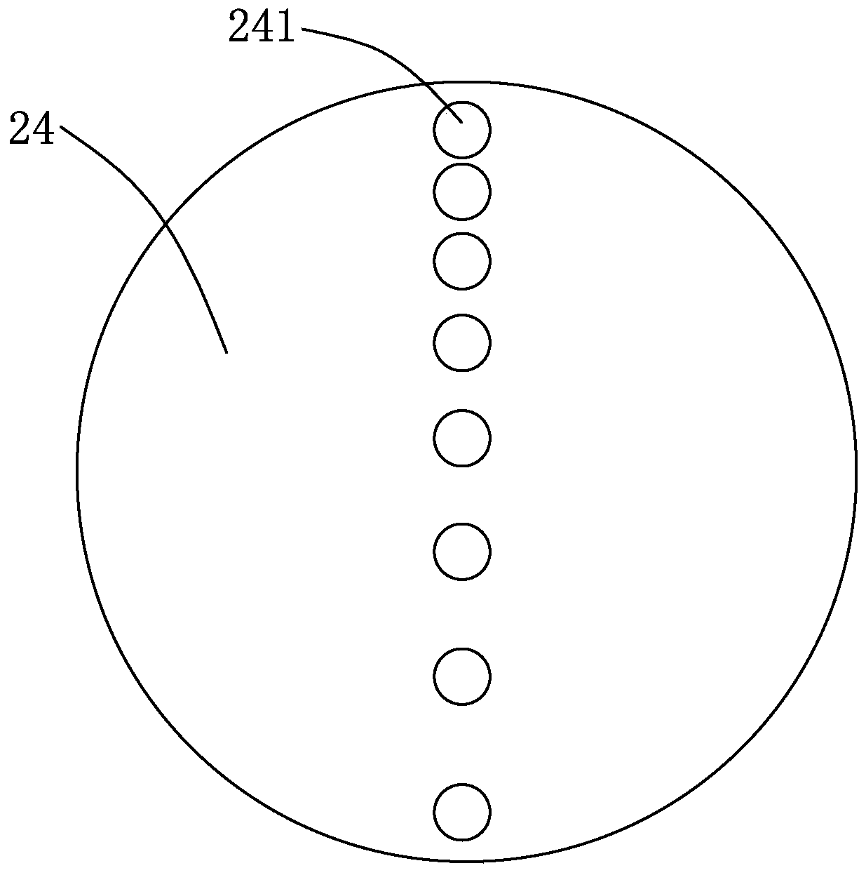
[0035] see again image 3 ,for figure 1 Schematic diagram of the second embodiment of the separator in the horizontal reactor shown. Each of the partitions 24 is provided with a plurality of diversion holes 241, and the diversion holes 241 are distributed along the depth direction of the material in the reaction chamber 111, that is, the diversion holes 241 correspond to different liquid levels. . The opening ratio of the guide flow holes 241 on each of the separators 24 is 0.02%-10%.

[0036] Along the direction from the bottom to the top of the reaction chamber 111 , the distance between two adjacent guide flow holes 241 gradually decreases, that is, the number of openings of the guide flow holes 241 at ...

Embodiment 3

[0040] The structure of the horizontal reactor in this embodiment is basically the same as that in Example 1, the difference lies in the distribution of the guide flow holes in the separator. The partition structure of this embodiment will be described in detail below.

[0041] see again Figure 4 ,for figure 1 The structural schematic diagram of Embodiment 3 of the separator in the horizontal reactor shown. Taking three consecutive partitions as an example, along the flow direction of the material, the three partitions are successively represented as 34a, 34b, 34c, and each of the partitions 34a, 34b, 34c is respectively provided with several guides. The flow holes are indicated as 341a, 341b, 341c, respectively.

[0042] The guide flow holes 341a, 341b, 341c are respectively distributed along the depth direction of the materials in the reaction chamber 111 . The opening ratio of the corresponding guide holes 341a, 341b and 341c on each of the separators 34a, 34b and 34c ...


PUM


Abstract

The invention provides a horizontal reactor. The horizontal reactor comprises a housing having a containing space, a feed inlet, a discharge port and multiple separator plates. The feed inlet and the discharge port are respectively arranged at two ends of the housing. The multiple separator plates are successively arranged at intervals along the direction vertical to flow direction of a material flowing from the feed inlet to the discharge hole. The multiple separator plates divide the containing space into multiple reaction chambers. The separator plates match the cross section of the housing in shape and size. Each of the separator plates is provided with several division holes which are distributed along the depth direction of the material in the reaction chambers. The horizontal reactor provided by the invention has high production capacity and can completely eradicate backmixing phenomenon of reactants.

Description

technical field [0001] The invention relates to the technical field of chemical equipment, in particular to a horizontal reactor. Background technique [0002] In the field of chemical technology, horizontal reactors are mostly used for liquid-liquid phase or liquid-solid phase reactions. In the prior art, the reactor is mostly designed as a multi-stage reactor, and the reactants are reacted step by step through the multi-stage reaction chamber to form a continuous reaction process and achieve the purpose of increasing the production capacity of the reactor. [0003] In the related art, the horizontal reactor uses multiple overflow plates to divide the reactor into multiple reaction chambers, and the materials in the upper-stage reaction chamber overflow through the top of the overflow plate to the next-stage reaction chamber, forming a continuous reaction chamber. reactor. However, during the working process of the multi-stage reactor, the liquid level in each reaction ch...

Claims


Application Information

Patent Timeline
Patent Type & Authority Patents(China)
IPC IPC(8): B01J19/18
CPCB01J19/006B01J19/1862B01J2219/00768
Inventor 艾秋红罗和安吴剑黄荣辉
Owner XIANGTAN UNIV
Why Eureka
Try Eureka