Combined type magnetic frame

A magnetic frame and combined technology, applied in the field of magnetic frames, can solve the problems of loss of magnetic beads, unoptimized shape and position of magnets, inseparability, etc. effect of loss

Inactive Publication Date: 2016-06-15
瀚吉康生物科技(北京)有限公司
View PDF11 Cites 3 Cited by
  • Summary
  • Abstract
  • Description
  • Claims
  • Application Information

AI Technical Summary

Problems solved by technology

[0004] 1) Most of the magnets and micro-test tube racks are designed as an integrated and inseparable structure. Users need to repeat the transfer of micro-test tubes one by one between the magnetic force frame and the ordinary micro-test tube rack.
[0005] 2) The hole for placing the micro-test tube is designed as a regular circle, and at the same time, in order to adapt to the diameter difference of the micro-test tubes of many manufacturers, the diameter of the hole is forced to be greater than the maximum diameter of the micro-test tube found on the market, so that most The micro-test tube cannot be reliably fixed in the hole, and the process of overturning and mixing cannot be completed
[0006] 3) After the micro-test tube is put into the hole, the flange of the tube mouth fits closely with the upper plane of the shelf, making it difficult to remove the micro-test tube
[0007] 4) The shape and position of the magnet are not optimized, so that the formed magnetic bead aggregates are loose and close to the bottom of the tube, and the magnetic beads are lost at the same time during the washing process (such as using a vacuum pump to pump out the liquid)
[0008] 5) Micro test tubes that cannot adapt to various tube bottoms

Method used


Image

  • Combined type magnetic frame
  • Combined type magnetic frame
  • Combined type magnetic frame

Examples


Embodiment 1

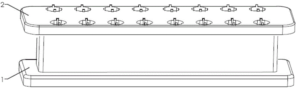
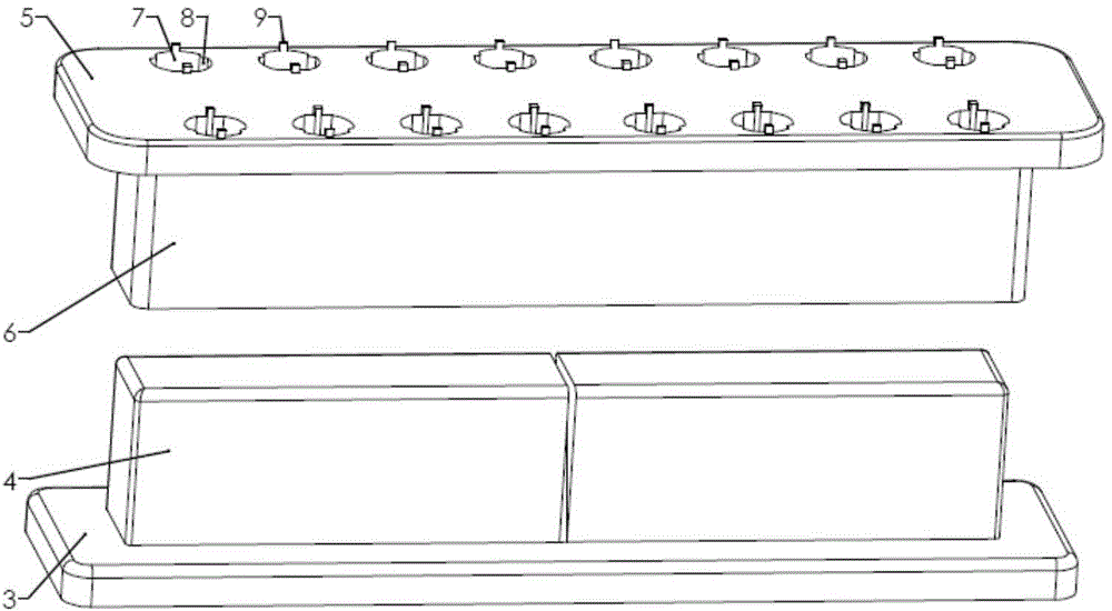
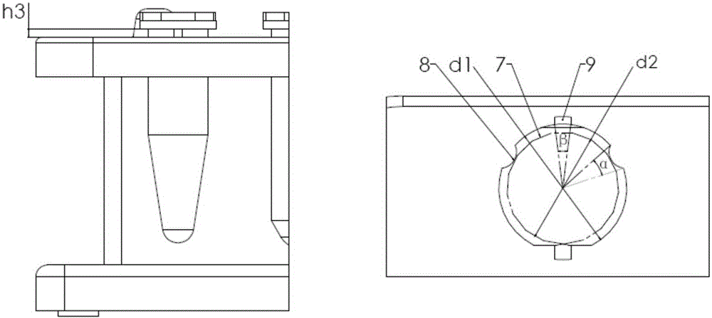
[0030] like figure 1 and figure 2 As shown, the magnetic frame includes a separable and combined magnet frame 1 and a micro test tube frame 2; the magnet frame 1 is mainly composed of a magnet frame base 3 and a column part 4 which is vertically fixed on the magnet frame base 3 and is provided with a magnet. The micro test tube rack 2 is mainly composed of a micro test tube rack flat plate 5 and a column part 6 with a cavity structure vertically fixed on the micro test tube rack flat plate 5 lower ends; the column part 6 with a cavity structure is vertically fixed on the magnet The cylinder part 4 that is provided with the magnet on the frame base 3 is matched to realize the separation and combination of the magnet frame 1 and the micro test tube frame 2; the column part 6 with the cavity structure can also be used as the micro test tube frame 2 The base; the thickness (h) of the micro test tube rack plate 5 is 7mm, and there are micro test tube holes 7 for placing micro tes...

Embodiment 2

[0034] like Image 6 and Figure 7 As shown, the magnetic frame includes a separable and combined magnet frame 1 and a micro test tube frame 2; the magnet frame 1 is mainly composed of a magnet frame base 3 and a column part 4 which is vertically fixed on the magnet frame base 3 and is provided with a magnet. The micro test tube rack 2 is mainly composed of a micro test tube rack flat plate 5 and a column part 6 with a cavity structure vertically fixed on the micro test tube rack flat plate 5 lower ends; the column part 6 with a cavity structure is vertically fixed on the magnet The cylinder part 4 that is provided with the magnet on the frame base 3 is matched to realize the separation and combination of the magnet frame 1 and the micro test tube frame 2; and the column part 6 with the cavity structure can also be used as a micro test tube frame The base of 2; the thickness (h) of described micro test tube rack flat plate 5 is 1-15mm, has the micro test tube hole 7 that is u...


PUM


Abstract

The invention discloses a combined type magnetic frame. The combined type magnetic frame provided by the invention comprises a magnet frame and a micro test tube frame. The magnet frame mainly comprises a magnet frame base and a column body part which is perpendicularly fixed to the magnet frame base and internally provided with magnets. The micro test tube frame mainly comprises a micro test tube frame flat plate and a column body part which is perpendicularly fixed to the lower end of the micro test tube frame flat plate and provided with a cavity structure. The column body part which is provided with the cavity structure is matched with the column body part which is perpendicularly fixed to the magnet frame base and internally provided with the magnets, so that separation and combination of the magnet frame and the micro test tube frame are achieved. The micro test tube frame flat plate is provided with micro test tube holes used for holding micro test tubes. The micro test tube holes are internally provided with flanges and boss bodies. Through the combined type magnetic frame provided by the invention, a user can conduct overturning, inclining, rotating, vibrating and other operations with the micro test tubes and the magnetic frame as a whole, and the work efficiency and the operation uniformity of a micro test tube chamber are improved exponentially.

Description

technical field [0001] The invention relates to a magnetic frame, in particular to a combined magnetic frame. Background technique [0002] The technology of using superparamagnetic magnetic beads to separate biomacromolecules in liquid phase has been widely used in the biomedical field, such as separating proteins, antibodies, and nucleic acids. When the liquid containing magnetic bead microparticles is put into the microtest tube, in the absence of magnetic force, the magnetic bead microparticles can be distributed in the liquid phase after stirring; but when the microtest tube is placed in a magnetic field, the superparamagnetic The magnetic bead microparticles are magnetized and attracted to the position with the strongest magnetic field, and gather into a tight group on the wall of the microtest tube. [0003] Although existing magnetic stand products can partially meet user requirements, there are many deficiencies. include: [0004] 1) Most of the magnets and micro...

Claims


Application Information

Patent Timeline
Patent Type & Authority Applications(China)
IPC IPC(8): B03C1/30
Inventor 李翠芬张建东
Owner 瀚吉康生物科技(北京)有限公司
Why Eureka
Try Eureka