Eureka AIR delivers breakthrough ideas for toughest innovation challenges, trusted by R&D personnel around the world.

Stamping control system and stamping method

A control system and punching technology, applied in the field of punching, to achieve the effect of reducing the probability of hidden dangers in production, improving safety and reducing the probability of damage

Active Publication Date: 2018-01-05
SHENZHEN TONGCHUAN TECH
View PDF6 Cites 2 Cited by
  • Summary
  • Abstract
  • Description
  • Claims
  • Application Information

AI Technical Summary

Problems solved by technology

[0004] Based on this, aiming at the above-mentioned problem of how to reduce the occurrence probability of production safety hazards in the traditional stamping control system, the present invention provides a stamping control system and a stamping method, which can reduce the occurrence probability of production safety hazards in the stamping control system

Method used


Image

  • Stamping control system and stamping method
  • Stamping control system and stamping method
  • Stamping control system and stamping method

Examples


Embodiment Construction

[0027] In order to explain the stamping control system and the stamping method provided by the present invention more clearly, the specific description will be given below in conjunction with the embodiments.

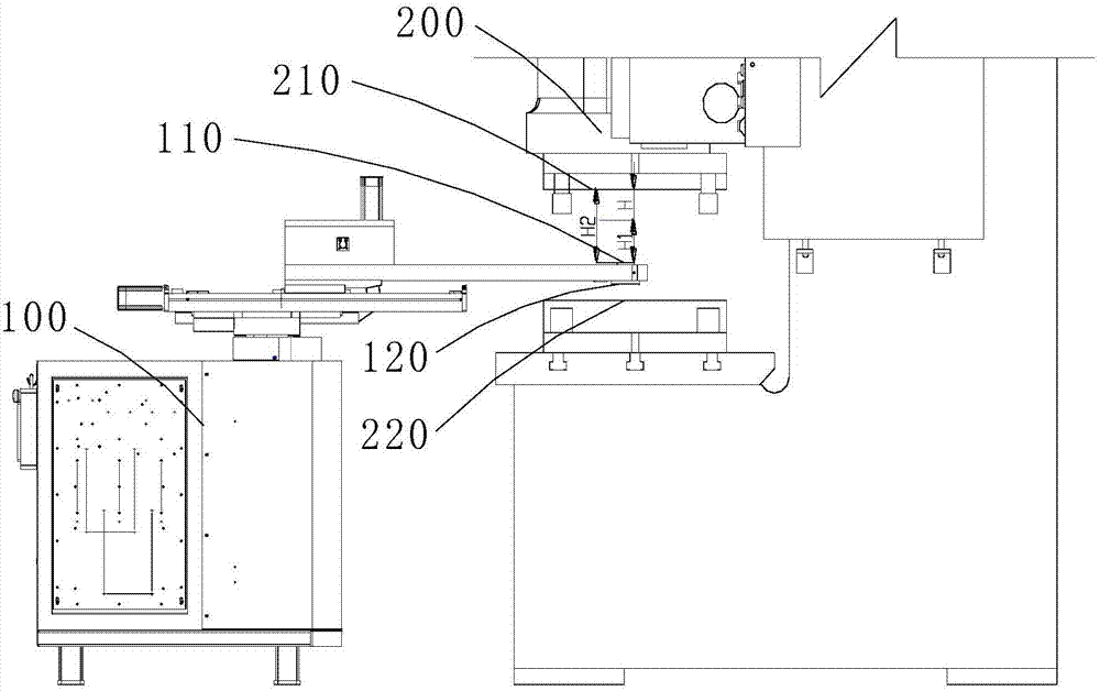
[0028] In one embodiment, as figure 1 As shown, the stamping control system includes a manipulator 100, a punch press 200 and a control system. The end of the manipulator is used to grip the material, and when the material is gripped, the material is kept on the lower surface 120 of the end of the manipulator. The punch press 200 has an upper die face 210 and a lower die face 220 .

[0029] Wherein, the control system is used to control the operation of the manipulator 100 and the punch press 200 , that is to say, this embodiment uses one system to control the manipulator 100 and the punch press 200 . Specifically, the control system is set in the manipulator 100 , that is, the manipulator 100 and the punch press 200 are controlled through a motion control card inside...


PUM


Abstract

The invention relates to a stamping control system and a stamping method. A manipulator and a stamping machine are controlled by virtue of one control system, and according to the control system, when the manipulator is located between an upper die surface and a lower die surface, an actual distance between the upper end surface of the tail end of the manipulator and the upper die surface is controlled to be greater than or equal to a safe distance, and the safe distance is 1 / 3 to 1 / 5 of a distance between the upper die surface and the lower die surface. The manipulator and the stamping machine stop running simultaneously as long as any of the manipulator and the stamping machine is failed, thus a risk in the traditional stamping control system is avoided that when any of the manipulator and the stamping machine is failed, the other one still runs, and at least the safe distance between the manipulator and the stamping machine can be ensured when the tail end of the manipulator is located between the upper die surface and the lower die surface; therefore, the safety of the manipulator and the stamping machine is further improved, and the occurrence probability of potential safety hazards of stamping control system production is reduced.

Description

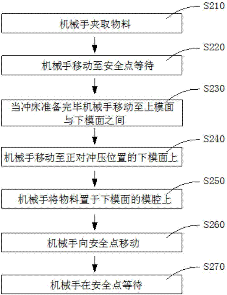
technical field [0001] The invention relates to the technical field of stamping, in particular to a stamping control system and a stamping method. Background technique [0002] The stamping control system usually includes a punch press and a manipulator. Usually, the control systems of the two are debugged separately, and then the coordination of the manipulator and the press is further debugged. During the punching operation, the manipulator first places the material in the punch press, and then when the manipulator moves out of the punch press and reaches a safe position, after a certain delay time, the manipulator sends a signal to the punch press, and the punch press executes the stamping operation after receiving the signal . [0003] However, during the entire operation of the above-mentioned stamping, the actions of the manipulator and the punching machine are asynchronous. The punching time is the sum of the moving time of the manipulator and the whole punching tim...

Claims


Application Information

Patent Timeline
Patent Type & Authority Patents(China)
IPC IPC(8): B21D55/00B21D22/06
CPCB21D22/06B21D55/00
Inventor 沈晓龙
Owner SHENZHEN TONGCHUAN TECH
Why Eureka
Eureka Blog
Learn More