Tightening device for assembling vehicle

A technology for vehicles and lifting devices, applied in vehicle parts, transportation and packaging, metal processing, etc., can solve problems such as complex structure, loose bolts, safety risks, etc., to achieve flexible and convenient movement, ensure tightening accuracy, and reduce labor intensity. Effect

Active Publication Date: 2016-06-15
DONGFENG PEUGEOT CITROEN AUTOMOBILE
View PDF6 Cites 9 Cited by
  • Summary
  • Abstract
  • Description
  • Claims
  • Application Information

AI Technical Summary

Problems solved by technology

[0002] When the existing tightening equipment assembles vehicle parts, the sleeve of the tightening equipment cannot rotate the servo wrench body during the process of rotating the bolt to reach the final angle, otherwise the rotation will interfere with the final bolt rotation angle, resulting in over-tightening or false tightening defects , Overtightening will cause the bolts to elongate or even break, and false tightening will cause the bolts to loosen during driving
Due to the large torque of the angle tightening equipment and the large reaction force during the tightening process, the requirements for the tightening equipment are relatively high, which cannot be achieved by manual assembly. Especially during the tightening process, the servo wrench must not shake or shake, otherwise the assembly accuracy will be greatly reduced. , because the final torque of the angle method is very large, if you hold the servo wrench by hand, you can’t hold it, and it may cause a safety risk
In the existing technology, the tightening equipment generally adopts robots or hard manipulators, and auxiliary braking devices, which have the defects of large volume, complex structure, and high manufacturing cost.

Method used


Image

  • Tightening device for assembling vehicle

Examples


Embodiment Construction

[0018] The present invention will be further described in detail below in conjunction with the accompanying drawings and specific embodiments to facilitate a clear understanding of the present invention, but they do not limit the present invention.

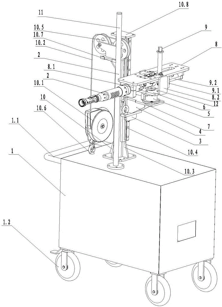
[0019] Such as figure 1 As shown, the present invention includes a mobile trolley 1, a lifting device 10 is fixed on the mobile trolley 1, the side of the lifting device 10 is slidably connected with the slider 3, and the upper part of the slider 2 is fixed with the lower fixing plate 7 of the bearing. connection, the fixed plate 7 under the bearing is set horizontally, the upper end of the fixed plate 7 under the bearing is fixed with the bottom of the sliding sleeve 5, the sliding sleeve 5 is located above the fixed plate 7 under the bearing, and the rotating shaft 12 is arranged inside the sliding sleeve 5 , the rotating shaft 12 is slidingly connected to the bearing upper fixing plate 6 through a bearing, the bearing upper fix...


PUM


Abstract

The invention relates to a tightening device for assembling a vehicle, and belongs to the technical field of automobile assembling equipment. The tightening device for assembling the vehicle comprises a moving trolley, wherein a lifting device is fixed on the moving trolley; a side surface of the lifting device is slidably connected with a slider; the upper part of the slider is fixedly connected with a bearing lower fixing plate; the bearing lower fixing plate is arranged horizontally; the upper end of the bearing lower fixing plate is fixed with the bottom of a sliding sleeve; the sliding sleeve is positioned above the bearing lower fixing plate; a rotating shaft is arranged in the sliding sleeve and is slidably connected with a bearing upper fixing plate penetrating through the rotating shaft through a bearing; the bearing upper fixing plate is positioned above the sliding sleeve and is arranged horizontally; a horizontal reaction plate is arranged above the bearing upper fixing plate, is fixedly connected with the bearing upper fixing plate, and is slidably connected with a reaction sleeve; and a servo wrench is fixed on the reaction plate. By the tightening device for assembling the vehicle, the problems that in a tightening assembling process, a force of reaction is over large and impacts people, and safety of people cannot be ensured are solved, and tightening precision is guaranteed.

Description

technical field [0001] The invention relates to the technical field of automobile assembly equipment, in particular to a tightening device for vehicle assembly. Background technique [0002] When the existing tightening equipment assembles vehicle parts, the sleeve of the tightening equipment cannot rotate the servo wrench body during the process of rotating the bolt to reach the final angle, otherwise the rotation will interfere with the final bolt rotation angle, resulting in over-tightening or false tightening defects , Overtightening will cause the bolts to elongate or even break, and false tightening will cause the bolts to loosen during driving. Due to the large torque of the angle tightening equipment and the large reaction force during the tightening process, the requirements for the tightening equipment are relatively high, which cannot be achieved by manual assembly. Especially during the tightening process, the servo wrench must not shake or shake, otherwise the a...

Claims


Application Information

Patent Timeline
Patent Type & Authority Applications(China)
IPC IPC(8): B23P19/06
CPCB23P19/06B23P2700/50
Inventor 邓东晓熊炘官建伟黄海冬翁天强
Owner DONGFENG PEUGEOT CITROEN AUTOMOBILE
Why Eureka
Try Eureka