
Numerical control molding equipment based on FDM technique

A kind of molding equipment and technology, applied in the field of industrial manufacturing, can solve the problems of easy deformation, weak shear resistance, stretching ability, and restriction of processing and molding, so as to avoid the decline of part strength, various structural filling paths, and strict guarantee symmetrical effect

Active Publication Date: 2016-06-15
陕西欧卡电子智能科技有限公司
View PDF3 Cites 6 Cited by
  • Summary
  • Abstract
  • Description
  • Claims
  • Application Information

AI Technical Summary

Problems solved by technology

[0006] The existing FDM technology 3D printer still has the following disadvantages in the molding process: the bottom plate has three degrees of freedom relative to the extrusion nozzle, and can move along the three directions of X / Y / Z. Axially stacked layer by layer to form a three-dimensional component
The choice of the bottom surface of the molding has a great influence on the slicing method and the molding process. The protruding part of the component, the hollow shell, the hole and other structures often need to be supported before the printing process, and are prone to deformation during the processing
The manufactured components are anisotropic in mechanical properties, and the interlayer shear and stretch resistance of the components is very weak, which also restricts the processing and molding of complex stressed components by the existing FDM technology 3D printers
[0007] When using existing FDM molding equipment for component processing, in order to avoid or optimize these problems, it is often necessary to avoid the appearance of some complex shapes in component design, and the single forming process also limits the use of additive manufacturing for parts processing. DEVELOPMENT OF DESIGN METHODS

Method used


Image

  • Numerical control molding equipment based on FDM technique
  • Numerical control molding equipment based on FDM technique
  • Numerical control molding equipment based on FDM technique

Examples


specific Embodiment approach

[0045] It should be noted that the structures, proportions, sizes, etc. shown in the drawings attached to this specification are only used to match the content disclosed in the specification, for those who are familiar with this technology to understand and read, and are not used to limit the implementation of the present invention Any modification of the structure, change of the proportional relationship or adjustment of the size shall still fall within the scope of the technical content disclosed in the present invention without affecting the effect and the purpose of the present invention. within the scope covered.

[0046] At the same time, terms such as "upper", "lower", "left", "right", "middle" and "one" quoted in this specification are only for the convenience of description and are not used to limit this specification. The practicable scope of the invention and the change or adjustment of its relative relationship shall also be regarded as the practicable scope of the...


PUM


Abstract

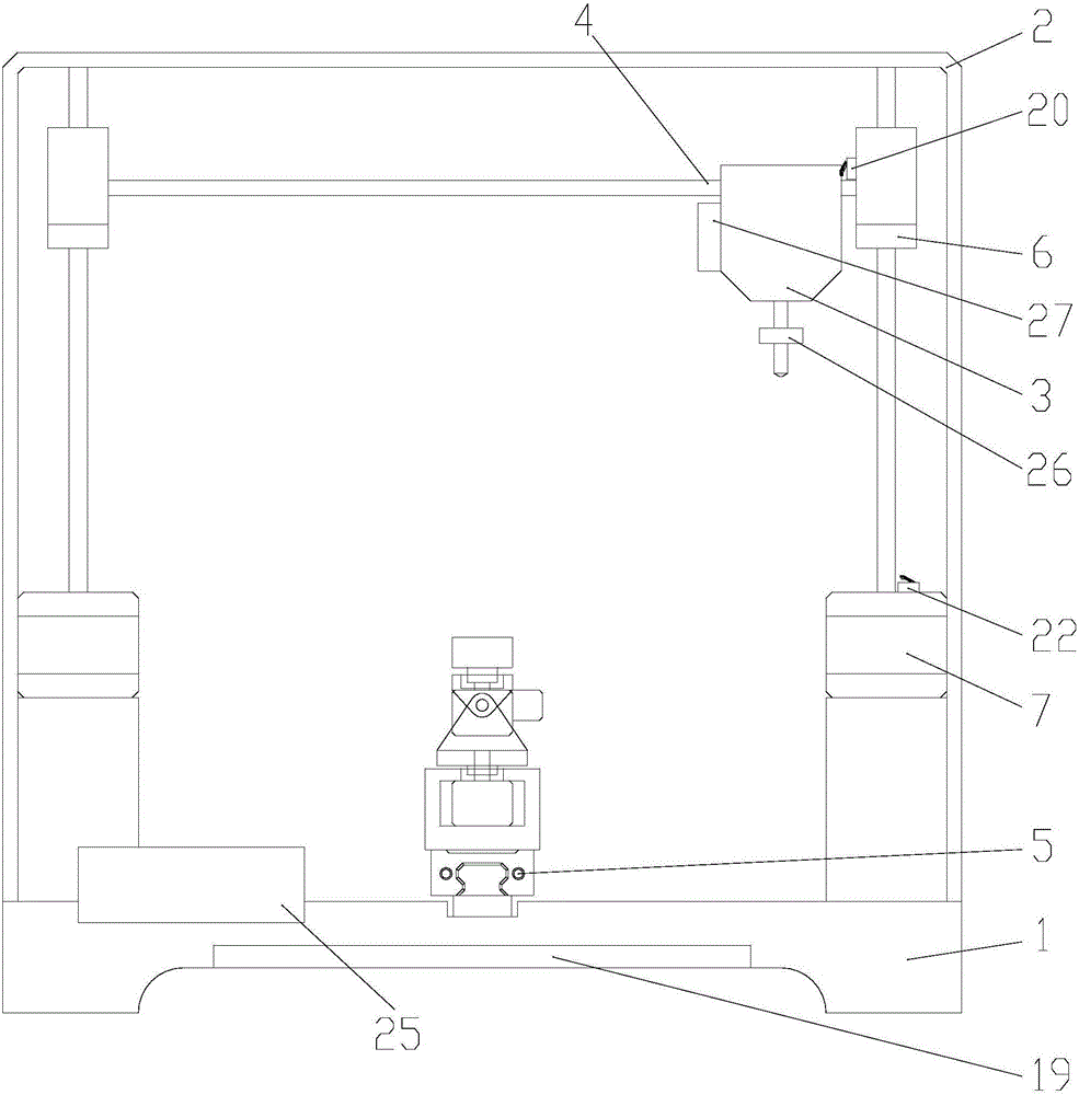
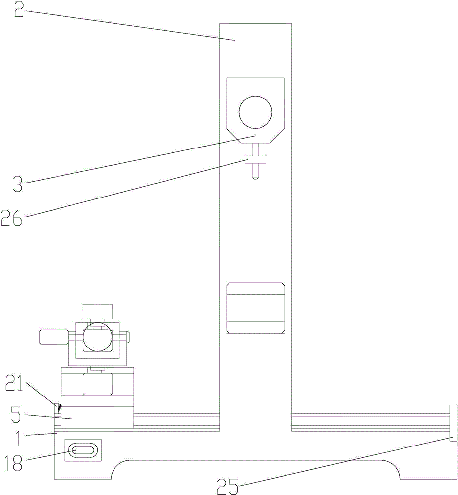
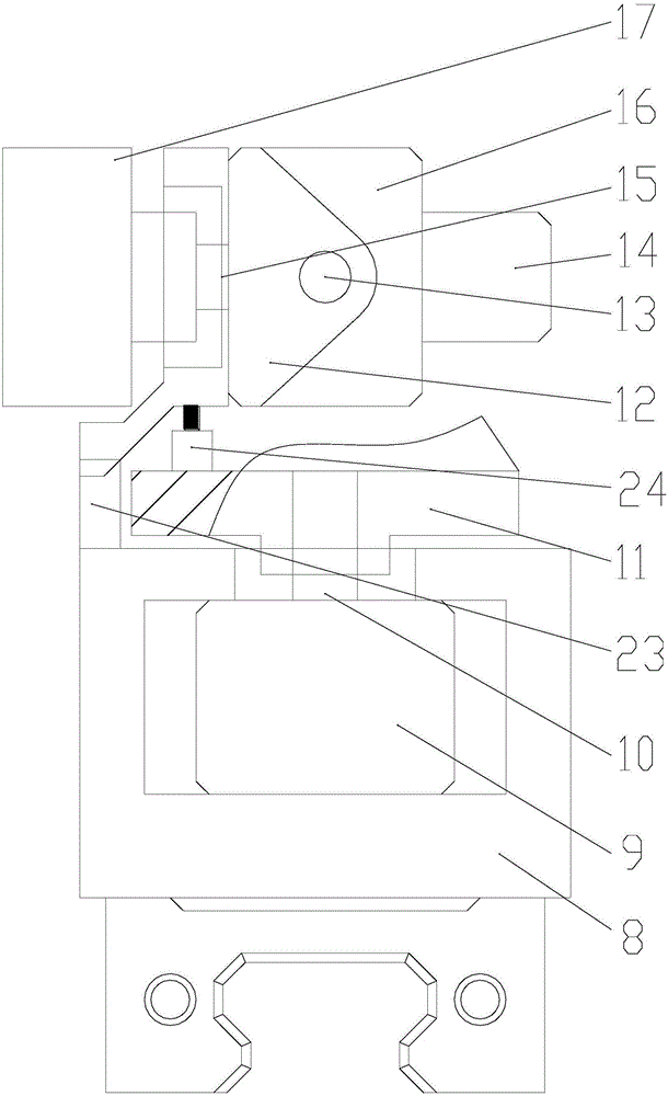
The invention discloses numerical control molding equipment based on an FDM (fused deposition modeling) technique. The numerical control molding equipment comprises an X-Y-Z axial translation component, an A-B-C axial rotating component and an electric control component, wherein the X-Y-Z axial translation component comprises a base, a frame, a material extruder, an X-direction linear guide track, a Y-direction linear guide track, a Z-axis lifting platform and a Z-axis screw rod stepper motor; the A-B-C axial rotating component comprises an A-axis motor base, an A-axis stepper motor, a B-axis motor rotating base, a B-axis stepper motor, a C-axis motor bracket, a C-axis stepper motor and a working chassis; the A-axis motor base is fixed on a sliding block of the Y-direction linear guide track; the A-axis stepper motor is mounted on the A-axis motor base and is used for driving the B-axis motor rotating base to rotate around an A-axis; the B-axis stepper motor is mounted on the B-axis motor rotating base and is used for driving the C-axis motor bracket to rotate around a B-axis; the C-axis stepper motor is mounted on the C-axis motor bracket and is used for driving the working chassis to rotate around a C-axis.

Description

technical field [0001] The invention belongs to the technical field of industrial manufacturing, and relates to a numerically controlled molding device based on fusion deposition (FDM) technology, which is used in related industrial manufacturing fields such as mold manufacturing, non-standard part production, complex structure processing and the like. Background technique [0002] FDM technology, that is, fused lamination technology, the abbreviation of Fused Deposition Modeling, can also be called fusion deposition technology, which is a kind of rapid prototyping technology. The material of this technology is generally a thermoplastic material, such as wax, ABS, PC, nylon, etc., and the material is supplied by wire. [0003] FDM technology is now mainly used in manufacturing equipment such as 3D printers. The process principle of 3D printers based on FDM mainly uses filamentous raw materials and fusible support materials to be transported upwards from the automatic loader ...

Claims


Application Information

Patent Timeline
Patent Type & Authority Applications(China)
IPC IPC(8): B29C67/00B33Y30/00B33Y50/02
CPCB33Y30/00B33Y50/02
Inventor 马申宇王哲
Owner 陕西欧卡电子智能科技有限公司
Learn More