Polar receiver using injection-locking technique

a technology of injection locking and polar receiver, which is applied in the direction of demodulation, radio transmission, electrical equipment, etc., can solve the problems of increasing circuit complexity and power consumption of the receiver, and the application of direct-conversion receivers is substantially limited, and achieves low cost and high energy efficiency. , the effect of great potential

Inactive Publication Date: 2013-06-06
NAT SUN YAT SEN UNIV
View PDF11 Cites 29 Cited by
  • Summary
  • Abstract
  • Description
  • Claims
  • Application Information

AI Technical Summary

Benefits of technology

[0004]In this invention, the polar receiver using injection-locking technique combines the injection-locking function of the first voltage-controlled oscillator with the first mixer and the second filter to separate an envelope component from a radio frequency signal received from the antenna. The polar receiver further combines the injection-locking function of the first voltage-controlled oscillator with the frequency discriminator and the third filter to separate a frequency-modulated component from a radio frequency signal received from the antenna. The envelope component and the frequency-modulated component can be digitally processed by the digital signal processing unit so as to accomplish radio frequency signal demodulation. Owing to simplicity, low cost and high energy efficiency of the present invention, the proposed polar receiver has great potential in applications for green radio.

Problems solved by technology

However, the direct-conversion receiver utilizes carrier recovery techniques based on phase-locked loop for achieving coherent demodulation function, which increases circuit complexity and power consumption of the receiver.
Therefore, the application of the direct-conversion receiver is substantially limited.

Method used


Image

  • Polar receiver using injection-locking technique
  • Polar receiver using injection-locking technique
  • Polar receiver using injection-locking technique

Examples


Embodiment Construction

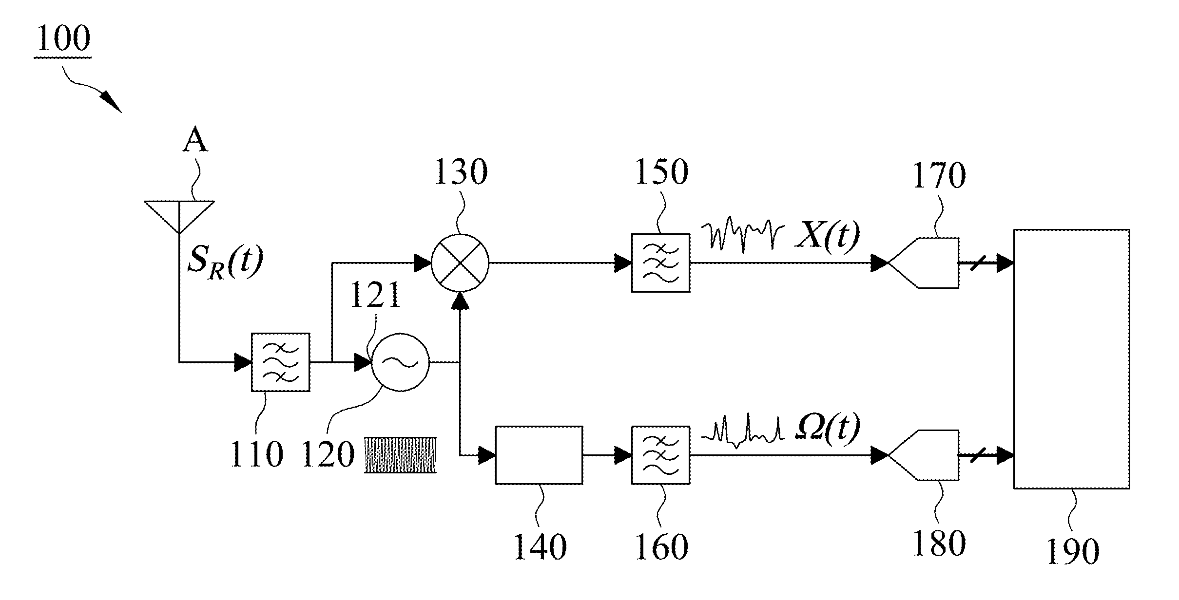
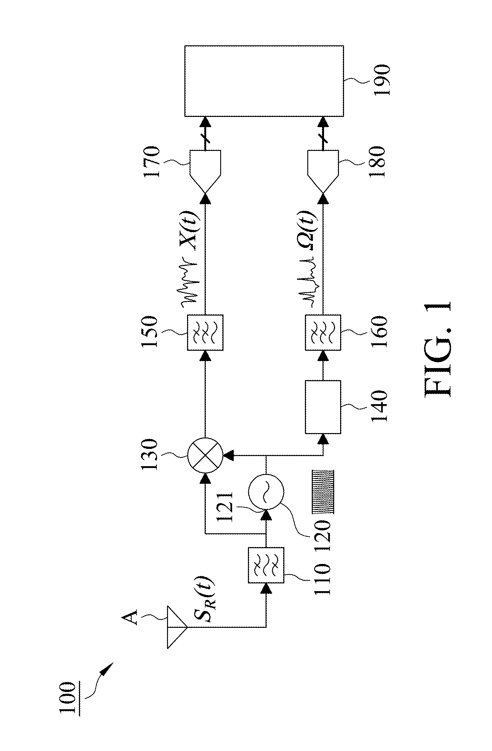
[0011]With reference to FIG. 1, a polar receiver using injection-locking technique 100 in accordance with a preferred embodiment of the present invention includes an antenna A, a first filter 110 electrically connected with the antenna A, a first voltage-controlled oscillator 120 electrically connected with the first filter 110, a first mixer 130 electrically connected with the first filter 110 and the first voltage-controlled oscillator 120, a frequency discriminator 140 electrically connected with the first voltage-controlled oscillator 120, a second filter 150 electrically connected with the first mixer 130, a third filter 160 electrically connected with the frequency discriminator 140, a first analog-digital converter 170 electrically connected with the second filter 150, a second analog-digital converter 180 electrically connected with the third filter 160, and a digital signal processing unit 190 electrically connected with the first analog-digital converter 170 and the second...


PUM


Abstract

A polar receiver using injection-locking technique includes an antenna, a first filter, a first voltage-controlled oscillator, a first mixer, a frequency discriminator, a second filter, a third filter, a first analog-digital converter, a second analog-digital converter and a digital signal processing unit. Mentioned polar receiver enables to separate an envelope signal and a frequency-modulated signal from a radio frequency signal received from the antenna via the injection locking technique of the first voltage-controlled oscillator and the frequency discriminator. The envelope component and the frequency-modulated component can be digitally processed by the digital signal processing unit to accomplish polar demodulation.

Description

FIELD OF THE INVENTION[0001]The present invention is generally related to a polar receiver, which particularly relates to the polar receiver using injection-locking technique.BACKGROUND OF THE INVENTION[0002]Conventional direct-conversion receiver is the most commonly used receiver architecture today for wireless communication. However, the direct-conversion receiver utilizes carrier recovery techniques based on phase-locked loop for achieving coherent demodulation function, which increases circuit complexity and power consumption of the receiver. Therefore, the application of the direct-conversion receiver is substantially limited.SUMMARY[0003]The primary object of the present invention is to provide a polar receiver using injection-locking technique including an antenna, a first filter electrically connected with the antenna, a first voltage-controlled oscillator electrically connected with the first filter, a first mixer electrically connected with the first filter and the first ...

Claims


Application Information

Patent Timeline
Patent Type & Authority Applications(United States)
IPC IPC(8): H04B1/06
CPCH03D5/00H04B1/0039
Inventor HORNG, TZYY-SHENGCHEN, CHI-TSANHSIAO, CHIEH-HSUNPENG, KANG-CHUN
Owner NAT SUN YAT SEN UNIV
Why Eureka
Try Eureka