
Pipe joint installation and positioning control system and method

A technology for installation, positioning and control systems, which is applied in water conservancy projects, artificial islands, underwater structures, etc., and can solve the problems of reduced installation and positioning accuracy of pipe joints, affecting the positioning accuracy and deviation of pipe joints to be installed, etc.

Active Publication Date: 2016-06-15
CCCC FIRST HARBOR ENG +1
View PDF5 Cites 8 Cited by
  • Summary
  • Abstract
  • Description
  • Claims
  • Application Information

AI Technical Summary

Problems solved by technology

Although the absolute coordinates of the pipe joints can be measured by the total station method or the GPS method, as the distance between the pipe joints to be installed and the installed pipe joints continues to shrink, the water entry depth of the pipe joints gradually increases. Deformation will cause a deviation between the actual coordinates of each feature point on the pipe joint and the coordinates calculated according to the results of the total station method or GPS method, which will affect the connection between the pipe joint to be installed and the installed pipe joint. The positioning accuracy of the pipe joints, resulting in a decrease in the installation and positioning accuracy of the pipe joints

Method used

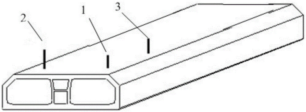
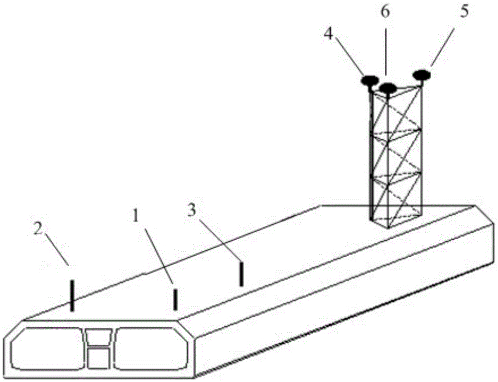
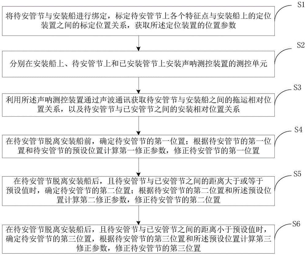

Image

  • Pipe joint installation and positioning control system and method
  • Pipe joint installation and positioning control system and method
  • Pipe joint installation and positioning control system and method

Examples


Embodiment Construction

[0042] The specific embodiments of the present invention will be further described below in conjunction with the accompanying drawings. The following examples are only used to illustrate the technical solution of the present invention more clearly, but not to limit the protection scope of the present invention.

[0043] The pipe joint installation positioning control system provided by the first embodiment of the present invention includes: a control device, a positioning device and a sonar measurement and control device;

[0044] The positioning device is fixedly arranged on the installation ship of the pipe joint to be installed, and is used to obtain the position parameters of the positioning device;

[0045] The sonar measurement and control device includes measurement and control units respectively installed on the installation ship, on the pipe joint to be installed and on the installed pipe joint;

[0046] The sonar measurement and control device is used to obtain the ...


PUM


Abstract

The invention relates to the technical field of engineering surveying, in particular to a pipe joint installation and positioning control system and method. The pipe joint installation and positioning control system provided by the invention comprises a positioning device arranged on an installing ship and used for obtaining position parameters of the positioning device, a sonar measuring and control device and a control device. The sonar measuring and control device is used for obtaining the relative towage position relation between a to-be-installed pipe joint and the installing ship and the relative installing position relation between the to-be-installed pipe joint and an already installed pipe joint through sonic wave communication. The control device is used for determining the current position of the to-be-installed pipe joint according to data measured by the positioning device and the sonar measuring and control device and outputting correcting parameters according to the current position and the preset position of the to-be-installed pipe joint so as to correct the current position. According to the pipe joint installation and positioning control system, the positioning device is arranged on the installing ship, and the to-be-installed pipe joint is positioned by means of the positioning device and the sonar measuring and control device so that the situation that the positioning accuracy of the to-be-installed pipe joint is affected due to deformation of survey towers in water can be avoided and accordingly the accuracy of control over pipe joint installation and positioning is improved.

Description

technical field [0001] The invention relates to the technical field of engineering measurement, in particular to a pipe joint installation positioning control system and method. Background technique [0002] With the progress of society and the development of science and technology, pipe section tunnels are more and more widely used in water transportation projects. The pipe section method tunnel construction is to sink the prefabricated pipe sections into the water and excavate the trenches in advance. A construction method in which pipe joints are assembled and connected together in water. [0003] At present, the total station method and the GPS method are commonly used methods for locating pipe joints in the water-saving sinking and docking construction. These two methods usually install a measurement tower at the beginning and end of the pipe joint, and set up a GPS positioning system or a prism on each measurement tower to perform absolute positioning of the pipe join...

Claims


Application Information

Patent Timeline
Patent Type & Authority Applications(China)
IPC IPC(8): E02D29/073E02D33/00
CPCE02D29/073E02D33/00E02D2250/0061
Inventor 林鸣李一勇刘德进李进高纪兵李增军岳铭滨刘兆权赵坤锁旭宏徐良陶振杰张秀振伍绍博
Owner CCCC FIRST HARBOR ENG
Learn More