
Double U-groove and joint node structure using same

A node structure, U-shaped groove technology, applied in building components, building structures, building insulation materials, etc., can solve the problems of screw top cap corrosion, difficult repair, shorten the life of screws, etc., to ensure aesthetics and decoration. , to ensure the effect of unity

Inactive Publication Date: 2016-06-15
DUOWEI UNION GRP
View PDF6 Cites 5 Cited by
  • Summary
  • Abstract
  • Description
  • Claims
  • Application Information

AI Technical Summary

Problems solved by technology

[0003] In the existing technology, double U-shaped grooves usually use double-color plate U-shaped grooves, such as Figure 5 as shown, Figure 5 It is a schematic diagram of the installation of the joint node structure using the double-color plate U-shaped groove in the prior art. The strength of the double-color plate U-shaped groove is low, and the connection between the large groove and the small groove depends on friction. After a long period of use It is easy to fall off, difficult to repair, and it is easy to cause corrosion of the screw top cap, which greatly reduces the life of the screw, which in turn affects the life of the house, and at the same time affects the appearance of the house structure

Method used


Image

  • Double U-groove and joint node structure using same
  • Double U-groove and joint node structure using same
  • Double U-groove and joint node structure using same

Examples


Embodiment Construction

[0039] In order to make the purpose, technical solutions and advantages of the embodiments of the present invention clearer, the technical solutions in the embodiments of the present invention will be clearly and completely described below in conjunction with the drawings in the embodiments of the present invention. Obviously, the described embodiments It is a part of embodiments of the present invention, but not all embodiments. Based on the embodiments of the present invention, all other embodiments obtained by persons of ordinary skill in the art without creative efforts fall within the protection scope of the present invention.

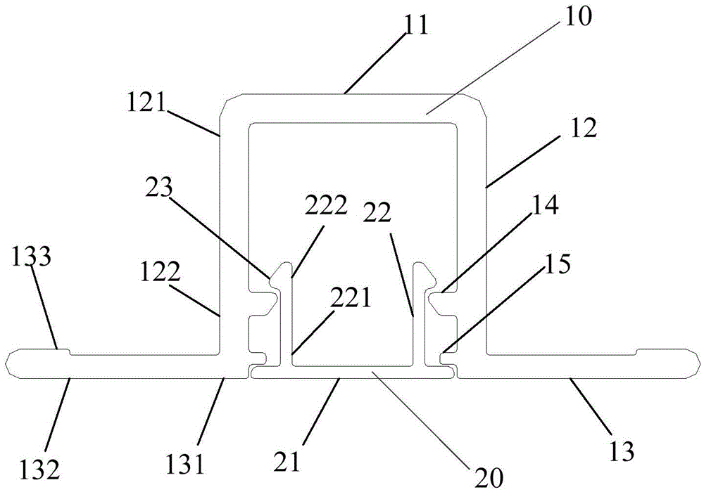
[0040] In the prior art, when multiple wall panels are installed, there will be a gap between the two wall panels, usually a spacer and double U-shaped grooves are arranged in the gap between the two wall panels, and the double U The purpose of the groove is to hide the screws to prevent them from being corroded, and at the same time cover the gap...


PUM


Abstract

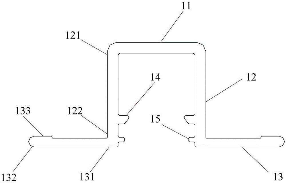
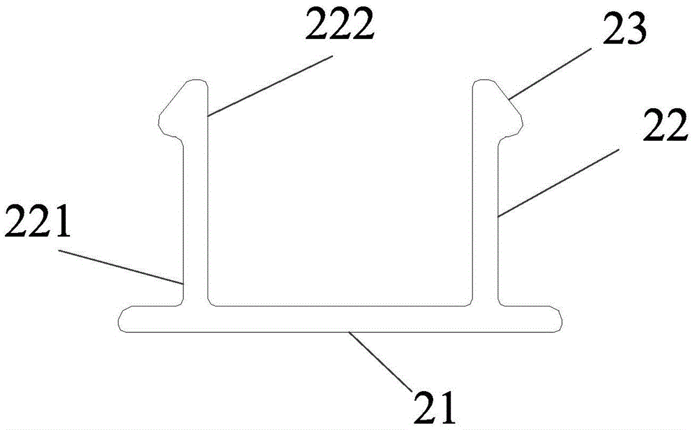
The embodiment of the present invention provides a double U-shaped groove and a joint structure using the double U-shaped groove. The double U-shaped groove includes: a first U-shaped groove and a second U-shaped groove; The first U-shaped groove includes a groove The top, the two side walls of the grooves, and the two groove edges, wherein the first ends of the side walls of each groove are respectively connected to opposite ends of the groove top, and the second ends of the side walls of each groove are located on the same side of the top of the groove and are respectively connected to each The first end of the groove edge and the second end of each groove edge extend in a direction away from the side wall of the groove, and a first flange and a second flange are provided on the opposite inner wall surfaces of the side walls of each groove; the second U-shaped The slot includes a cover plate and two support plates, wherein each support plate is located on the same side of the cover plate, and the first end of each support plate is respectively connected to the cover plate, and the second end of each support plate is respectively provided with limit hooks Correspondingly, a joint joint structure using double U-shaped grooves is provided, which has high strength and is not easily deformed, and the double-supporting and limiting technology of reverse hooks ensures the integrity and decoration of the double U-shaped grooves.

Description

technical field [0001] The embodiment of the present invention relates to the technical field of building construction, and in particular to a double U-shaped groove and a joint joint structure using the double U-shaped groove. Background technique [0002] At present, when installing wall panels, especially when installing through multiple wall panels, there will be a gap between the two wall panels. Usually, a spacer is set in the gap between the two wall panels, and screws are used to fix the gap between the two wall panels. The cushion block is fixedly connected with the purlins of the house. When connecting the cushion block, there is also a pair of U-shaped grooves on the cushion block. The purpose of setting the double U-shaped groove is to hide the screws to prevent the screws from being corroded, and to cover the gap. Make the building more beautiful. [0003] In the existing technology, double U-shaped grooves usually use double-color plate U-shaped grooves, such ...

Claims


Application Information

Patent Timeline
IPC IPC(8): E04B1/68
CPCE04B1/68E04B1/6806
Inventor 卜祥显高建武宋士宇
Owner DUOWEI UNION GRP
Learn More