
A Moment of Inertia Compensation Method Considering Time Delay Applicable to Wind Turbine Simulator

A technology of moment of inertia and compensation method, which is applied in the monitoring of wind turbines, wind turbines, machines/engines, etc., to achieve obvious improvement effects and simple and easy methods

Active Publication Date: 2018-10-02
NANJING UNIV OF SCI & TECH
View PDF4 Cites 0 Cited by
  • Summary
  • Abstract
  • Description
  • Claims
  • Application Information

AI Technical Summary

Problems solved by technology

But there is no relevant description in the prior art

Method used


Image

  • A Moment of Inertia Compensation Method Considering Time Delay Applicable to Wind Turbine Simulator
  • A Moment of Inertia Compensation Method Considering Time Delay Applicable to Wind Turbine Simulator
  • A Moment of Inertia Compensation Method Considering Time Delay Applicable to Wind Turbine Simulator

Examples


Embodiment III

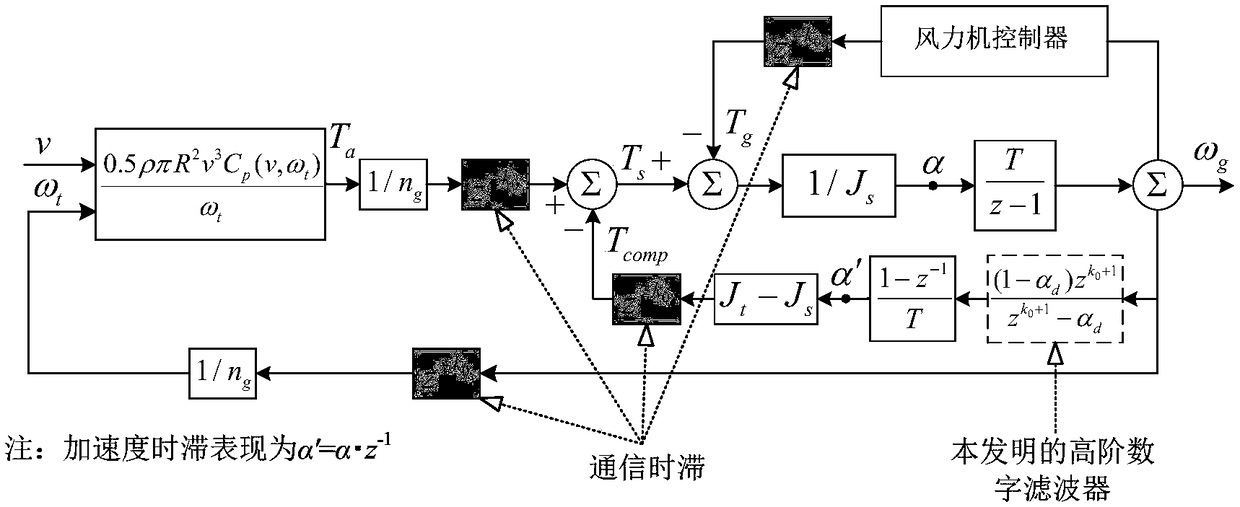
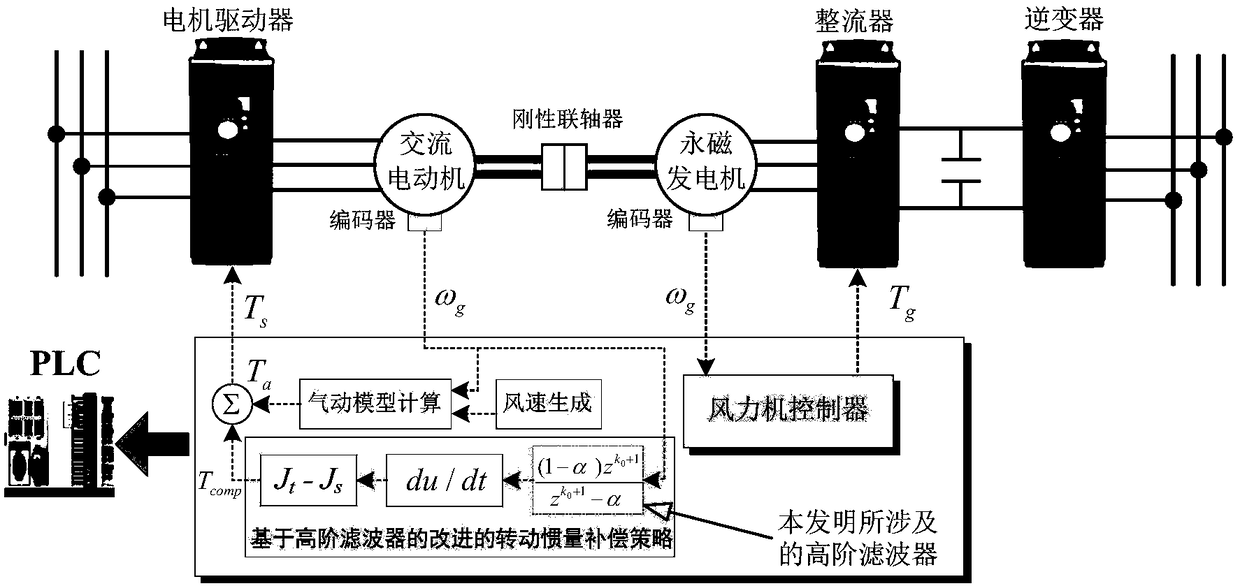
[0050] Embodiment III: apply the moment of inertia compensation method considering the time lag of the present invention, such as figure 1 As shown in , the specific implementation is the following steps:

[0051] 1. Determine the moment of inertia J of the wind turbine simulator t =0.0845;

[0052] 2. Determine the moment of inertia J of the wind turbine to be simulated t , at this time it is 0.4225kgm 2 (i.e. 5J s );

[0053] 3. Measure the communication time lag τ in the wind turbine simulator, select the simulator control period T = 20ms, and calculate the order k of the communication time delay at this time 0 =[τ / T]=4;

[0054] 4. Add a 5th-order digital filter to the dynamic torque compensation branch of the wind turbine simulator;

[0055] 5. According to the moment of inertia J of the simulator s and wind turbine moment of inertia J t The parameter α of the 5th-order digital filter is adjusted, and according to the formula in claim 3, α is taken as 0.8 at this...

Embodiment IV

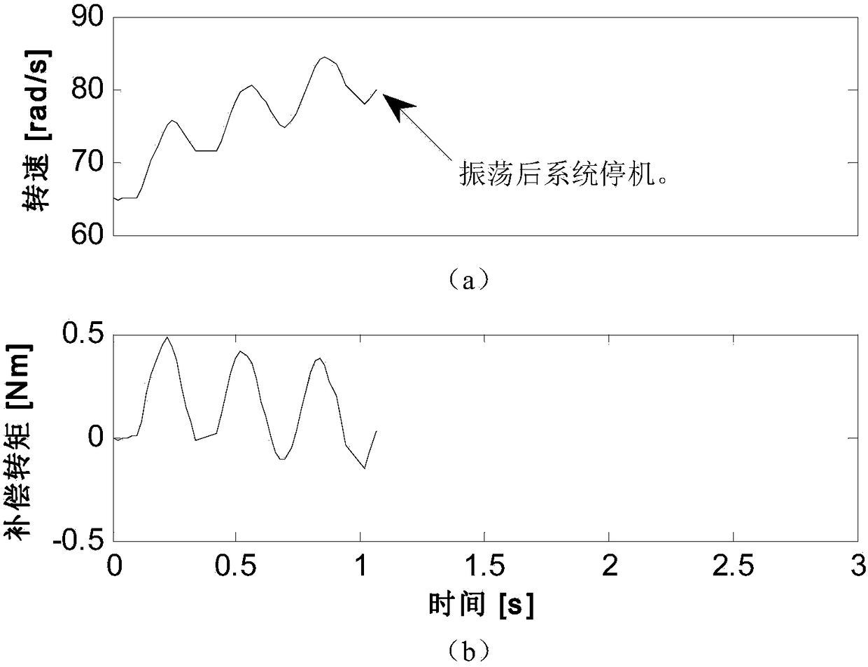
[0057] Embodiment IV: Apply the time-lag-considered moment of inertia compensation method of the present invention, the specific steps are the same as in embodiment III, and compare and study the WTS of input turbulent wind under different simulated moments of inertia. Such as Figure 6 It can be seen that no instability occurred during the experiment. The improved moment of inertia compensation method based on the high-order filter of the present invention can overcome the influence of time lag, so that the wind turbine simulator can stably simulate the slow mechanical dynamic process of the wind turbine with large multiples of moment of inertia.

[0058] It can be seen from the above that an improved moment of inertia compensation method of the present invention that considers communication time lag and acceleration time lag solves the oscillation problem of the compensation torque by introducing a high-order filter to eliminate the deviation response component excited by th...


PUM


Abstract

The invention discloses an improved rotational-inertia compensation method considering a communication time lag and an acceleration time lag.The problem that when a present wind turbine simulator simulates a large-rotational-inertia wind turbine, instability and vibration occur is solved.The compensation method includes the steps that a wind turbine simulator is tested to determine the rotational inertia of the wind turbine simulator; a wind turbine model simulated by the wind turbine simulator is determined, and the rotational inertia of the wind turbine model is determined; the wind turbine simulator is tested to determine the step length of the communication time lag; a filter is added into a dynamic-torque compensation branch circuit of the wind turbine simulator according to the situation; the parameters of the digital filter are adjusted, and the wind turbine simulator stably runs.By means of the compensation method, the instability problem, caused by the communication time lag and the acceleration time lag, of the WTS is solved, the WTS can stably simulate the large-rotational-inertia wind turbine in the mode that the influence of the time lag is eliminated, and a user is assisted in conducting a control experiment of the wind turbine in the laboratory environment.

Description

technical field [0001] The invention belongs to the field of wind turbine simulators, and in particular relates to a moment of inertia compensation method suitable for wind turbine simulators considering communication time lag and acceleration time lag. Background technique [0002] As the actual wind turbine field experiment is very difficult and time-consuming, the wind turbine simulator (WindTurbine Simulator, WTS) is a kind of equipment that can conduct wind turbine experiments in the laboratory environment. In-depth research on blade aerodynamic design, wind turbine servo control, and electrical conversion technology is of great significance to the development, optimization, and field application of wind power generation systems. [0003] Since the physical moment of inertia of the WTS is much smaller than that of the actual wind turbine, the WTS must adopt a moment of inertia compensation method to restore the slow mechanical dynamic characteristics of the actual wind ...

Claims


Application Information

Patent Timeline
Patent Type & Authority Patents(China)
IPC IPC(8): F03D17/00G06F17/50
CPCG06F30/17G06F30/367Y02E60/00
Inventor 殷明慧刘尚孟李伟杰路英伟何立君沈春卜京谢云云姚娟蔡晨晓邹云
Owner NANJING UNIV OF SCI & TECH
Learn More