
Vibration and oscillation composite type road roller steel wheel

A road roller and composite technology, applied in the field of road roller steel wheels, can solve the problems of not being able to meet the requirements well, the work efficiency is reduced, the compaction method is single, etc., and achieves convenient processing, production and assembly, safe working process, and easy operation. Effect

Inactive Publication Date: 2015-07-29
CHANGAN UNIV
View PDF8 Cites 5 Cited by
  • Summary
  • Abstract
  • Description
  • Claims
  • Application Information

AI Technical Summary

Problems solved by technology

[0004] At present, the road rollers that appear at home and abroad are all independent vibratory rollers or oscillating rollers. There are few rollers that can vibrate and oscillate at the same time, and all of them can only achieve a single fixed amplitude, which is inevitable during the compaction process. Over-compacted or under-compacted ground will require repeated compaction, and the compaction method is too single, which cannot well meet the requirements of various working conditions
In this way, not only will the work efficiency be reduced, but also the cost will be increased, resulting in a waste of energy.

Method used


Image

  • Vibration and oscillation composite type road roller steel wheel
  • Vibration and oscillation composite type road roller steel wheel
  • Vibration and oscillation composite type road roller steel wheel

Examples


Embodiment Construction

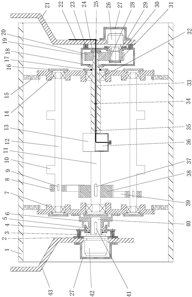
[0049] like figure 1 As shown, the present invention includes a cylindrical hollow wheel body 1, a hydraulic drive mechanism for driving the hollow wheel body 1, two wheel frames symmetrically arranged on the left and right sides of the hollow wheel body 1, and installed in the middle part of the inner side of the hollow wheel body 1. And the vibration shaft 11 arranged coaxially with the hollow wheel body 1 and the two vibration shafts 12 symmetrically arranged on both sides of the vibration shaft 11, the two vibration shafts 12 are arranged parallel to the vibration shaft 11 and both are located at Inside the hollow wheel body 1 , the two wheel frames are respectively the left wheel frame 43 and the right wheel frame 21 located on the left and right sides of the hollow wheel body 1 . An overrunning clutch 38 is installed on the vibrating shaft 11, and a driven gear 8 is coaxially installed on the two vibrating shafts 12, and the driven gear 8 installed on the two vibrating s...


PUM


Abstract

The invention discloses a vibration and oscillation composite type road roller steel wheel which comprises a hollow wheel body, a hydraulic driving mechanism, two wheel racks, a vibration shaft and two oscillation shafts, wherein the hydraulic driving mechanism is used for driving the hollow wheel body; the wheel racks are symmetrically arranged on the left side and the right side of the hollow wheel body; the vibration shaft is mounted in the middle of the inner side of the hollow wheel body; the oscillation shafts are symmetrically distributed on two sides of the vibration shaft; an overrunning coupler is mounted on the vibration shaft; driven gears are mounted on the oscillation shafts and are connected with the overrunning coupler; eccentric mechanisms are arranged on the outer sides of the oscillation shafts; a left mounting plate and a right mounting plate are symmetrically arranged inside the hollow wheel body; a driving disc which is in transmission connection with the hydraulic driving mechanism is mounted on the left mounting plate; a clutch driving mechanism in transmission connection with the right end of the vibration shaft is mounted on the right wheel rack. The vibration and oscillation composition road roller steel wheel is simple in structure, reasonable in design, simple and convenient to operate, good in use effect and flexible in use and operation mode, vibration and oscillation functions are integrated, and the problem that a conventional road roller steel wheel can only vibrate or oscillate can be effectively solved.

Description

technical field [0001] The invention relates to a road roller steel wheel, in particular to a vibrating and oscillating composite road roller steel wheel. Background technique [0002] The function of the road roller is to make the materials of the subgrade and the structural layers of the road surface have sufficient compactness, thereby reducing the permanent deformation caused by driving, and enhancing its impermeability and stability. The service life and performance are very important. [0003] Road rollers mainly include two types: vibratory rollers and oscillating rollers. The vibratory roller vibrates with the centrifugal force generated by the eccentric wheel, while the oscillating roller relies on the combination of the circumference of the oscillating wheel and the shaft core to form an elliptical oscillatory motion in the front and rear directions. accomplish. In actual use, the pressure wave of the vibratory roller can be transmitted to the depth, spread from ...

Claims


Application Information

Patent Timeline
Patent Type & Authority Applications(China)
IPC IPC(8): E01C19/28
CPCE01C19/286
Inventor 赵悟武甜林亮亮吕兴坤董晨希张衡冯忠绪
Owner CHANGAN UNIV
Learn More