
A potential energy conversion device

A conversion device, potential energy technology, applied in pipeline systems, gas/liquid distribution and storage, mechanical equipment, etc., can solve problems such as large consumption of electric energy or thermal energy, and achieve unique measures, scientific and rational structure, and innovative ideas.

Active Publication Date: 2018-10-30
吉县古贤泵业有限公司
View PDF8 Cites 0 Cited by
  • Summary
  • Abstract
  • Description
  • Claims
  • Application Information

AI Technical Summary

Problems solved by technology

[0002] Mine construction often needs to send water to high-altitude areas to form uplink materials, and then transport minerals to the ground to form downlink materials with water. The existing technology can only transport uplink materials and downlink materials separately, resulting in downlink materials with very large potential energy, so in At the end of the conveying process, a throttling orifice plate must be used for energy dissipation and decompression treatment; while for the upstream material, only pumping means can be used, which consumes a lot of electric energy or heat energy

Method used


Image

  • A potential energy conversion device

Examples


specific Embodiment

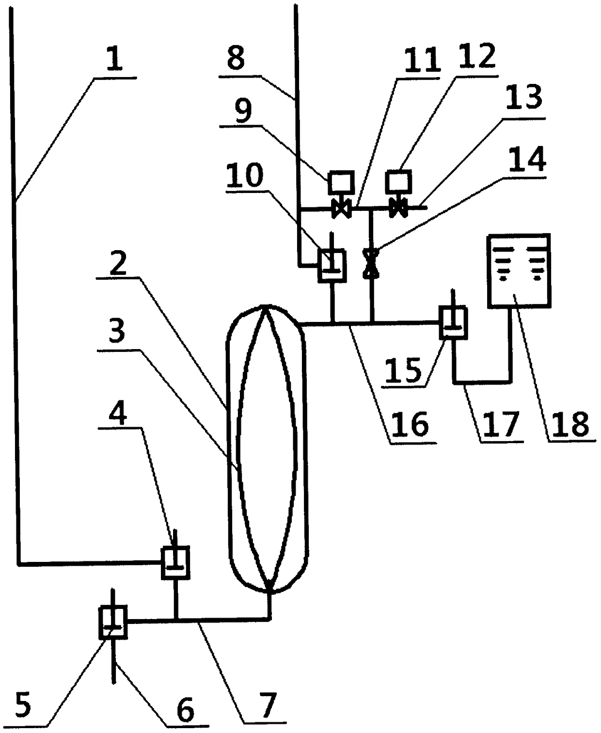
[0023] Under the control of the industrial control system, water, as the upward material, passes through the upward material feed valve (15) from the upward material buffer tank (18) along the pipeline four (17), and enters the pressure vessel (2) and the diaphragm (3) along the pipeline three (16). ), close the upstream material feed valve (15), open the pressure balance valve (9) between the upward material pipeline and the pressure vessel, and a small amount of upward material passes through the throttling buffer (14) along the three ( 16) Enter the pressure vessel (2), the internal pressure of the pressure vessel rises and reaches a pressure balance with the upward material pipeline, the industrial control system controls the downward material feed valve (4) to open, and the downward material with potential energy enters the pressure vessel (2) and the diaphragm In another space between (3), the pressure is transmitted to the upward material through the diaphragm (3), and t...


PUM


Abstract

The invention relates to a potential energy converting device. The potential energy converting device particularly comprises a downlink material feeding pipeline, a pressure container, an isolation membrane, a downlink material feeding valve, a downlink material discharging valve, a downlink material discharging pipeline, a pipeline I, an uplink material discharging pipeline, a pressure balancing valve, an uplink material discharging valve, a pipeline II, a pressure container air pressure balancing valve, an evacuation pipeline of the pressure container air pressure balancing valve, a throttling buffer, an uplink material feeding valve, a pipeline III, a pipeline IV and an uplink material buffer trough, wherein the pressure balancing valve is arranged between the downlink material pipeline and the pressure container. According to the potential energy converting device, downlink materials and uplink materials are isolated by virtue of the isolation of the isolation membrane, and meanwhile, the potential energy of the downlink materials are transferred to the uplink materials, so that the uplink materials can reach high-altitude terrains without consuming electric energy or heat energy.

Description

technical field [0001] The invention relates to the potential energy conversion between the downlink material and the uplink material in a mine, in particular to a potential energy conversion device for converting the potential energy of the downlink material into the uplink material. Background technique [0002] Mine construction often needs to send water to high-altitude areas to form uplink materials, and then transport minerals to the ground to form downlink materials with water. The existing technology can only transport uplink materials and downlink materials separately, resulting in downlink materials with very large potential energy, so in At the end of the conveying process, a throttling orifice must be used for energy dissipation and decompression treatment; for the upstream material, only pumping means can be used, which consumes a lot of electric energy or heat energy. Contents of the invention [0003] The purpose of the present invention is to provide a bran...

Claims


Application Information

Patent Timeline
Patent Type & Authority Patents(China)
IPC IPC(8): F17D1/12F17D3/01
CPCF17D1/12F17D3/01
Inventor 葛稳生
Owner 吉县古贤泵业有限公司
Learn More