Hydrothermal Single Well Water Analyzer

An analyzer, hydrothermal technology, applied in the direction of analyzing materials, instruments, scientific instruments, etc., can solve the problems of inaccurate measurement, stuck or blocked probe, low temperature of output liquid, etc., to achieve accurate measurement data and easy installation Low maintenance and production costs

Active Publication Date: 2017-12-12
JINZHOU JINYAN TECH
View PDF8 Cites 0 Cited by
  • Summary
  • Abstract
  • Description
  • Claims
  • Application Information

AI Technical Summary

Problems solved by technology

[0003] The purpose of the present invention is to solve the problem in the prior art that the probe is easily stuck or blocked due to the low temperature of the produced fluid, resulting in inaccurate measurement, and to provide a hydrothermal single-well water analyzer

Method used


Image

  • Hydrothermal Single Well Water Analyzer
  • Hydrothermal Single Well Water Analyzer
  • Hydrothermal Single Well Water Analyzer

Examples


Embodiment 1

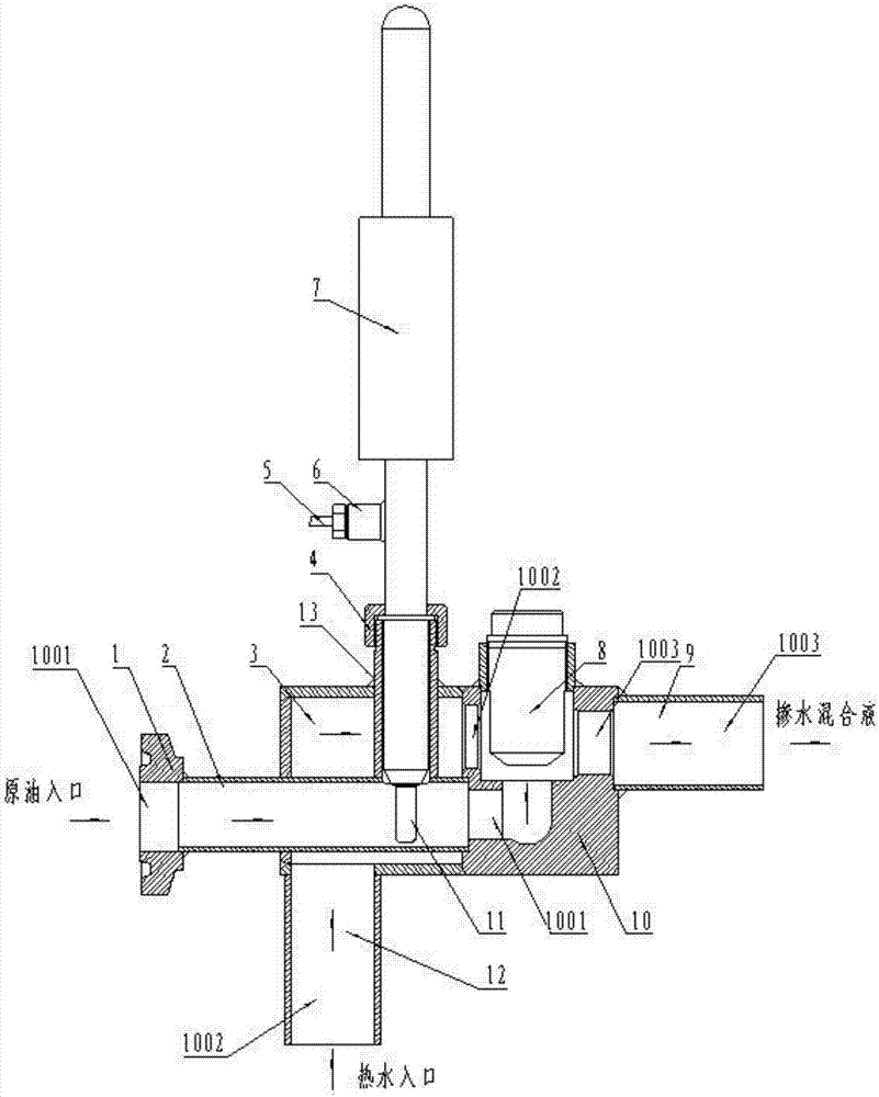
[0020] Such as figure 1 and figure 2 As shown, the present invention has a radio frequency moisture analyzer 7 and a water mixing valve. A lock nut 4, a signal cable 5, an electrical interface 6 and a probe 11 are arranged on the radio frequency moisture analyzer 7; a crude oil inlet 1001, a hot water inlet 1002 and a water-mixed liquid are arranged on the valve body 10 of the water-mixing valve The outlet 1003 is provided with a one-way valve 8 on the valve body 10 of the water-mixing valve, and the crude oil inlet 1001 and the hot water inlet 1002 communicate with the outlet 1003 of the water-mixed mixed solution through the one-way valve 8, and at the inlet of the water-mixing valve body 10 A hot water chamber 3 is arranged on the side, and a hot water pipeline 12 is arranged at the inlet end of the hot water chamber 3, and the hot water pipeline 12 passes through the hot water chamber 3, the hot water inlet 1002 of the water mixing valve body 10 and the water mixing valv...

Embodiment 2

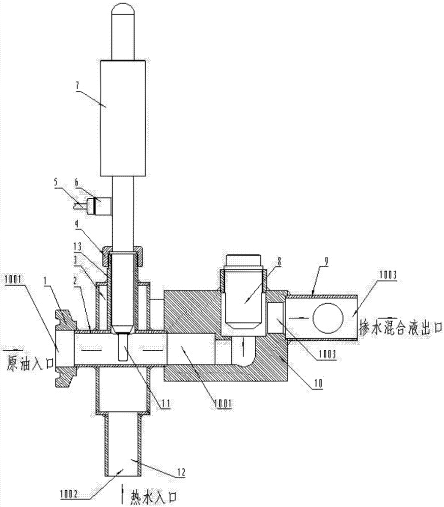
[0023] Such as image 3 and Figure 4 As shown, the hydrothermal single-well water cut analyzer includes a radio frequency water cut analyzer 7 and a water mixing valve, and a lock nut 4, a signal cable 5, an electrical interface 6 and a probe 11 are arranged on the radio frequency water cut analyzer 7; The water-mixed valve body 10 is provided with a crude oil inlet 1001 and a water-mixed solution outlet 1003, and the water-mixed solution outlet 1003 is connected with a water-mixed solution pipeline 9; Directional valve 8, the crude oil inlet 1001 communicates with the water-mixed liquid outlet 1003 through the one-way valve 8, a hot water chamber 3 is arranged on the inlet side of the water-mixed valve body 10, and a hot water pipeline is arranged at the inlet end of the hot water chamber 3 12. At the outlet end of the hot water chamber 3, a hot water outlet connecting pipe 14 communicating with the water-mixed liquid pipeline 9 is provided, and an oil well incoming oil pip...


PUM


Abstract

A hydrothermal single-well water cut analyzer solves the problem of inaccurate measurement due to the low temperature of the produced fluid and the probe is easily stuck or blocked, including a radio frequency water cut analyzer. The special feature of the probe is that the hydrothermal single-well water content analyzer is also equipped with a water mixing valve, on which a crude oil inlet and a water mixing liquid outlet are arranged on the valve body of the water mixing valve, and on the valve body of the water mixing valve A one-way valve is provided, the crude oil inlet communicates with the water-mixed liquid outlet through the one-way valve, a water-mixed liquid pipeline is connected to the water-mixed liquid outlet, and a hot water chamber is set on the crude oil inlet side of the water-mixed valve body, The hot water chamber communicates with the inner cavity of the water mixing valve or communicates with the water mixing liquid pipeline through the hot water outlet connecting pipe. An oil well incoming pipeline is worn in the hot water chamber, and the inlet of the oil incoming pipeline is located at The outside of the hot water chamber and the outlet communicate with the crude oil inlet, the radio frequency water content analyzer is set on the oil incoming pipeline and the probe is located in the oil incoming pipeline.

Description

technical field [0001] The invention belongs to a single well water content analyzer, in particular to a hydrothermal single well water content analyzer. Background technique [0002] At present, long-term and reliable on-line analysis and measurement of the water content of crude oil in a single well is a universal problem. Serious consequences of inaccurate measurement after being blocked or blocked. Contents of the invention [0003] The purpose of the present invention is to solve the problem in the prior art that the probe is easily stuck or blocked due to the low temperature of the produced fluid, resulting in inaccurate measurement, and provides a hydrothermal single-well water analyzer. [0004] The present invention is achieved like this: [0005] A hydrothermal single-well water-cut analyzer includes a radio-frequency water-cut analyzer, and a probe is arranged on the radio-frequency water-cut analyzer. The valve body of the water-mixing valve is provided with...

Claims


Application Information

Patent Timeline
Patent Type & Authority Patents(China)
IPC IPC(8): G01N33/28
CPCG01N33/2847
Inventor 朱广陞
Owner JINZHOU JINYAN TECH
Why Eureka
Try Eureka