
A Method for Dynamic Simulation of Industrial Pipeline Control Relationships

A control relationship and dynamic simulation technology, which is applied in the direction of comprehensive factory control, comprehensive factory control, electrical program control, etc., can solve the problems of inability to reflect the influence of control nodes, the stagnation of pipeline installation construction drawings, and the inability to fully demonstrate the power of nodes to global pipeline control relationship issues

Active Publication Date: 2018-01-09
中国科学院沈阳计算技术研究所有限公司
View PDF5 Cites 0 Cited by
  • Summary
  • Abstract
  • Description
  • Claims
  • Application Information

AI Technical Summary

Problems solved by technology

[0003] At present, in the field of industrial production, the construction drawings for pipeline installation still remain in two-dimensional plans, axonometric drawings, and perspective drawings. This series of drawings can show the control relationship at each node, but cannot reflect the impact of subsequent control nodes. Comprehensively display the powerful relationship of specific nodes to global pipeline control
This traditional display method cannot meet the needs of real-time control decision-making for pipeline control associations

Method used


Image

  • A Method for Dynamic Simulation of Industrial Pipeline Control Relationships
  • A Method for Dynamic Simulation of Industrial Pipeline Control Relationships

Examples


Embodiment Construction

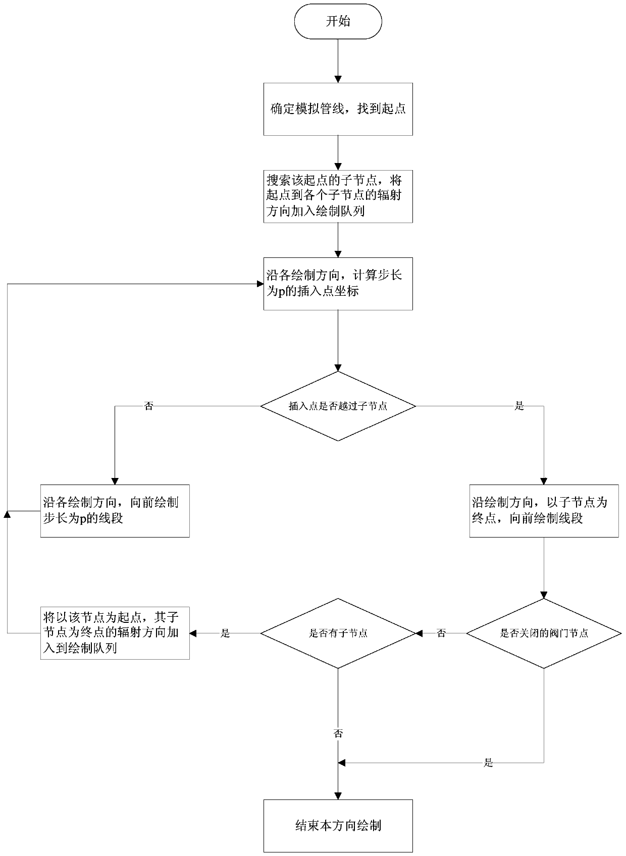
[0017] Combine below figure 1 , 2 And embodiment the present invention is described in further detail.

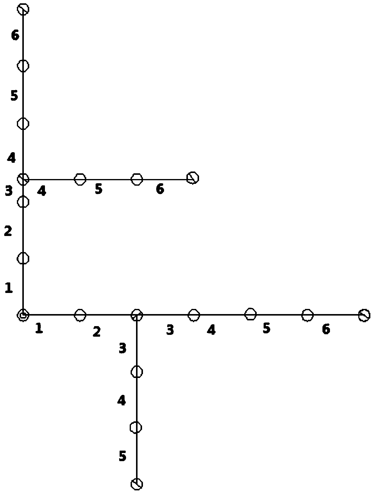
[0018] Step 1: First model the simulation pipeline, the starting point of the pipeline is as follows figure 2 shown is the starting point of the pipeline, the inflection point and valve control points , the pipeline is abstracted as a polyline segment composed of starting point, inflection point, and valve control point.

[0019] Step 2: Take the starting point of the pipeline as figure 2 shown As the starting point, search for its child nodes, and then draw a line segment with a step size of P along the direction of each child node. There is no specific requirement for the value of P. The smaller the value is, the more realistic the simulation will be but the longer it will take. An appropriate value can be obtained by experimenting according to the specific situation.

[0020] Step 3: After two draws, the horizontal direction has reached a valve control node...


PUM


Abstract

The invention relates to a method for dynamically simulating the industrial pipeline control relationship, comprising the following steps: S1, modeling industrial pipelines; S2, numbering vertices in S1, inputting the three-dimensional coordinates and types of the vertices and the initial state of a logic control point into a database, and recording the number of the father node of each vertex; S3, in a first time period, drawing a line segment of which the step length is P along each child node direction of a starting point of pipelines by starting from the starting point, judging the type and state of each child node of the starting point, ending drawing in the direction if the child node in the direction is a valve control node and is closed, or, executing next step; and S4, circulating the steps until drawing in all the directions is ended. The method has the advantages of visual display, data reusability and settable relationship and state.

Description

technical field [0001] The invention relates to the field of industrial control simulation, in particular to a method for dynamically simulating the control relationship of industrial pipelines. Background technique [0002] In the field of industrial production, various pipelines are intertwined and intricate. Whether the material flow control in the pipeline is stable or not determines whether industrial production can be carried out efficiently and orderly. Due to the complexity of the pipeline laying environment, it is not easy to quickly find the pipeline control nodes according to the needs of industrial production, and it is not easy to implement the flow control and disposal of the substances in the pipeline. Therefore, the research on industrial pipeline control simulation has important practical significance. [0003] At present, in the field of industrial production, the construction drawings for pipeline installation still remain in two-dimensional plans, axonom...

Claims


Application Information

Patent Timeline
Patent Type & Authority Patents(China)
IPC IPC(8): G05B19/418
CPCY02P90/02
Inventor 郭向坤李想修腾飞赵冰雪
Owner 中国科学院沈阳计算技术研究所有限公司
Learn More