Dual-display winding machine of shaping rotor

A winding machine and rotor technology, which is applied in the field of double-display winding machines for shaping rotors, can solve the problems of operators’ palm damage, difficulty in ensuring winding quality, and large volume of shaping rotors, so as to achieve convenient installation, improve work efficiency and The effect of applicability, wide application and promotion prospect

Inactive Publication Date: 2016-06-15
GUANGXI LUZHOU MACHINERY MFG
View PDF7 Cites 2 Cited by
  • Summary
  • Abstract
  • Description
  • Claims
  • Application Information

AI Technical Summary

Problems solved by technology

At present, the winding work of the motor rotor coil is still mainly realized manually. After the enameled wire is rolled out from the wire, the worker will press the enameled wire to the motor rotor blade and wind it tightly, and manually realize the side-by-side winding of the same layer of enameled wire. Rigidity, winding quality is difficult to guarantee, and the workers need a large winding force while winding the wire, and the enameled wire rubs in the hand, which will also cause great damage to the palm of the operator, and because the shaping rotor is large in size, it is relatively cumbersome , it is extremely inconvenient to disassemble and change the direction of the shaping rotor after the winding is full

Method used


Image

  • Dual-display winding machine of shaping rotor
  • Dual-display winding machine of shaping rotor
  • Dual-display winding machine of shaping rotor

Examples


Embodiment 1

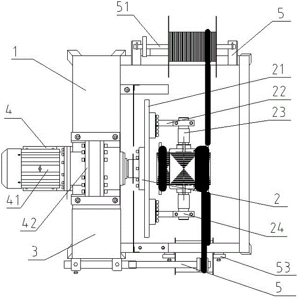
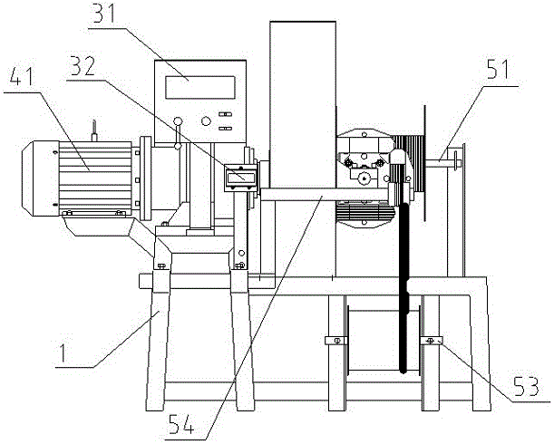
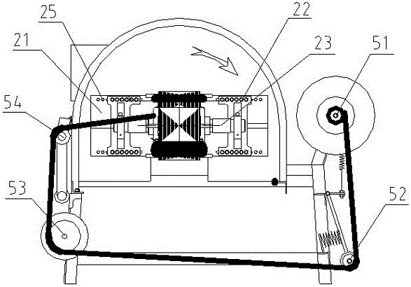
[0022] As shown in the figure, a shaping rotor double-display winding machine includes a working frame 1, a rotor clamp 2, a driving device 4 and a coil clamp 5; the driving device 4 is installed on the working frame 1; the rotor clamping 2 includes a rotating plate 21, a bracket 22, and a rotor shaft 23; the rotating plate 21 is installed on the driving shaft of the driving device 4, and rotates following the rotation of the driving shaft; the supporting frame 22 is provided with two, respectively On the rotating plate 21, it is located on both sides of the connecting point between the rotating plate 21 and the drive shaft; the bracket 22 is provided with a mounting plate 24; the mounting plates 24 on the two brackets 22 correspond to each other, and the rotor shaft 23 can Assembled on the rotor fixture 2 through the two mounting plates 24;

[0023] The coil fixture 5 is arranged corresponding to the rotor fixture 2 , and the coil assembled on the coil fixture 5 is in the sam...


PUM


Abstract

The invention provides a dual-display winding machine of a shaping rotor. The dual-display winding machine comprises a workbench, a rotor fixture, a driving device and a coil fixture, wherein the driving device is arranged on the workbench, the rotor fixture comprises a rotation plate, supports and a rotor shaft, the rotation plate is arranged on a driving shaft of the driving device and rotates with the rotation of the driving shaft, the supports are arranged on the rotation plate and is used for fixing the rotor shaft, installation plates are arranged on the supports, the rotor shaft can be assembled on the rotor fixture by the two installation plates, the coil fixture is arranged in correspondence to the rotor fixture, the rotation direction of a coil assembled on the coil fixture is consistent with the rotation direction of the rotor fixture, the rotor fixture can be driven to rotate on a vertical surface, a plurality of support installation holes are formed in the rotation plate, the installation positions of the two supports can be adjusted, and the rotor shaft is movably arranged on the supports and can be convenient to disassemble. The dual-display winding machine has the advantages of reasonable structural design and a good processing effect, and is simple to install.

Description

technical field [0001] The invention relates to the field of coil winding, in particular to a double-display winding machine for shaping rotors. Background technique [0002] In the production of motor rotors, an essential process is to wind the enameled wire into the wire groove. During the winding process, the enameled wire is required to be tightly wound on the rotor blades, and the enameled wires of the same layer are also required to be tightly side by side. Because the enameled wire The hardness itself is relatively high, which increases the difficulty of winding and greatly reduces work efficiency. At present, the winding work of the motor rotor coil is still mainly realized manually. After the enameled wire is rolled out from the wire, the worker will press the enameled wire to the motor rotor blade and wind it tightly, and manually realize the side-by-side winding of the same layer of enameled wire. Rigidity, winding quality is difficult to guarantee, and the worke...

Claims


Application Information

Patent Timeline
Patent Type & Authority Applications(China)
IPC IPC(8): H02K15/09
CPCH02K15/09
Inventor 朱祖锋李庚荣梁海著
Owner GUANGXI LUZHOU MACHINERY MFG
Why Eureka
Try Eureka