

Servo system, and encoder
一种医学成像系统、微波发射的技术,应用在医学成像系统领域,能够解决昂贵、复杂布线等问题
- Summary
- Abstract
- Description
- Claims
- Application Information
AI Technical Summary
Problems solved by technology
Method used
Image

Examples
Embodiment Construction
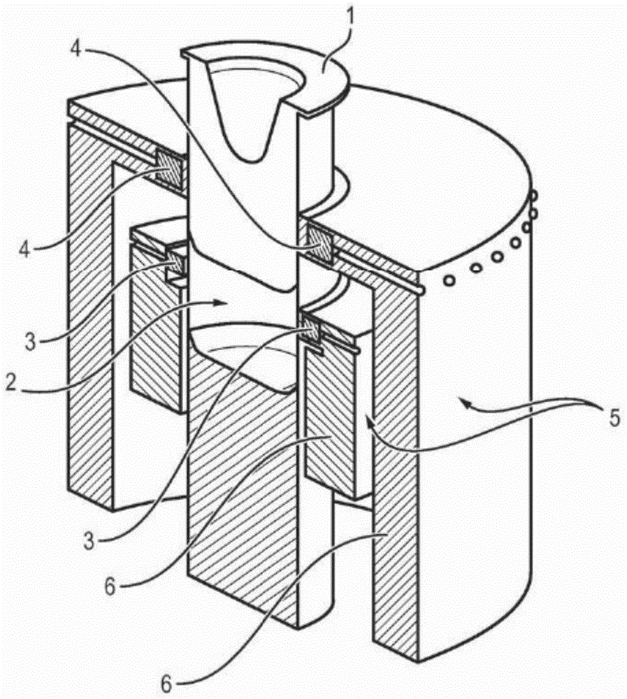
[0028] exist figure 1 In an embodiment of the present invention, the device comprises a housing 1 made of a dielectric material, a container 2, at least one array 3 of transmitting probes 3a, at least one array 4 of receiving probes 4a, and a set of metal shells 5 and The electromagnetic absorber 6 made of foam, the shell 1 is used to receive the patient's breast, the shell 1 is arranged in the container 2, the set of metal shell layers 5 and the foam made Electromagnetic absorber 6 surrounds container 2 and arrays 3 and 4 .
[0029] The housing 1 held in the container 2 has an external shape (cylindrical in this example) complementary to the internal shape of the container. The housing has a hollow cavity for receiving the patient's breast.
[0030] The housing 1 is detachable relative to the container 2 . The device is connected to a set of housings 1 . The outer shapes of the housings in the set of housings are identical. But the cavities are different and can be adapt...
PUM
 Abstract
Description
Claims
Application Information