Engine device

An engine and supercharger technology, applied in the directions of engine components, combustion engines, machines/engines, etc., can solve the problems of increasing the height of the engine and the inability to easily load ships, so as to improve the maintenance workability and simplify the gas supply. Effects of cooling structure and simplified support structure

Active Publication Date: 2016-06-15
YANMAR POWER TECHNOLOGY CO LTD
View PDF8 Cites 2 Cited by
  • Summary
  • Abstract
  • Description
  • Claims
  • Application Information

AI Technical Summary

Problems solved by technology

[0008] In the structure in which a high-pressure supercharger or an aftercooler is mounted on the upper surface of the engine as in Patent Document 1, there is a problem that the installation height of the engine becomes large and cannot be easily mounted on a ship where the installation height of the engine is limited. Wait

Method used


Image

  • Engine device
  • Engine device
  • Engine device

Examples


Embodiment Construction

[0037] Next, an embodiment in which the present invention is embodied will be described based on the drawings in the case of being applied to a diesel engine of a power generator mounted on a ship.

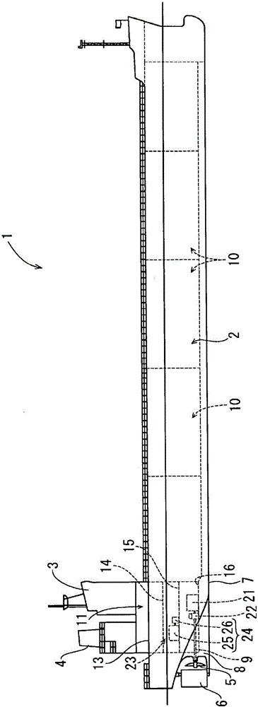
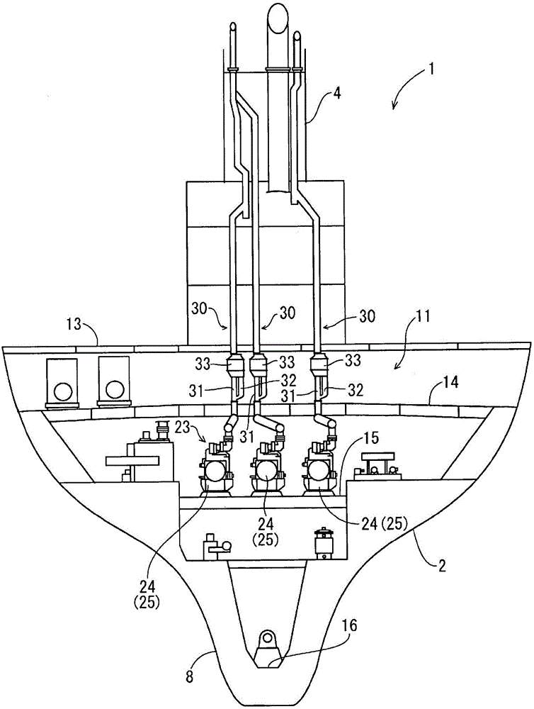
[0038] First, refer to figure 1 and figure 2 , the outline of the ship 1 equipped with a diesel engine will be described. like figure 1 and figure 2 As shown, the ship 1 is equipped with: a hull 2; a cockpit 3 (bridge) arranged on the stern side of the hull 2; a ventilator 4 (chimney) arranged behind the cockpit 3; The propeller 5 for propulsion and the rudder 6 for steering. In addition, a stern skeg (Japanese: skeg) 8 is integrally formed on the bottom 7 of the rear lower part of the hull 2 ​​, and a propulsion shaft 9 for rotating and driving a propeller 5 for propulsion is provided, and the propulsion shaft 9 is pivotally supported on the stern skeg 8 . The cabin 10 is provided in the bow side and the center part in the hull 2. As shown in FIG. An engine room 11 is pro...


PUM


Abstract

The present invention addresses the problem of providing an engine device which enables a support structure of a first supercharger (56) and a second supercharger (58) to be simplified, and which enables an air cooling structure of an engine (25) to be simplified. Provided is an engine device in which a first supercharger (56) and a second supercharger (58) are provided in series to a midpoint of an exhaust-gas discharge path of an engine (25). The engine device is a structure in which the first supercharger (56) and the second supercharger (58) are provided to one side surface of the engine (25). The second supercharger (58) is provided close to the one side surface of the engine (25), and the first supercharger (56) is provided at a distance from the one side surface of the engine (25).

Description

technical field [0001] The present invention relates to an engine device mounted on a ship or the like, and relates to an engine device including a two-stage supercharger (high-pressure supercharger, low-pressure supercharger), etc., which burn fuel efficiently. Background technique [0002] In the past, for example, in prior art documents, there is a technology that includes a high-pressure supercharger and a low-pressure supercharger, and suppresses an increase in the temperature of the air supplied to the engine while increasing the air supply pressure of the engine to achieve combustion efficiency. improvement (for example, refer to Patent Document 1, Patent Document 2, etc.). [0003] prior art literature [0004] patent documents [0005] Patent Document 1: Japanese Patent Application Laid-Open No. 06-66146 [0006] Patent Document 2: International Publication No. 2012 / 016712 Contents of the invention [0007] The problem to be solved by the invention [0008] I...

Claims


Application Information

Patent Timeline
Patent Type & Authority Applications(China)
IPC IPC(8): F02B37/00F02B37/013
CPCF01N2590/02F02B37/004F02B37/013F02B67/10F02M35/10157F02M35/10268F02M35/165Y02T10/12F02M26/08F02M26/09F02M26/32
Inventor 滨冈俊次西浦文浩横山哲也
Owner YANMAR POWER TECHNOLOGY CO LTD
Why Eureka
Try Eureka