
Rail device with material positioning mechanism

A material positioning and track technology, used in conveyors, conveyor objects, transportation and packaging, etc., can solve the problems of complex positioning mechanism structure, increase equipment failures, affect production work and other problems, achieve good positioning effect, reduce equipment failures, The effect of improving production efficiency

Inactive Publication Date: 2016-06-22
ZHONGSHAN MEIJIESHI PACKAGING PROD
View PDF3 Cites 2 Cited by
  • Summary
  • Abstract
  • Description
  • Claims
  • Application Information

AI Technical Summary

Problems solved by technology

[0002] At present, in the production process of emulsion pumps and spray valves, the materials produced in each process need to be transported to the next process through rails. There are often positioning mechanisms in the rails. The existing positioning mechanisms are relatively complicated in structure and easy to scratch. material or hinder the passage of subsequent materials
This will affect normal production work, increase equipment failure, and reduce production efficiency

Method used


Image

  • Rail device with material positioning mechanism
  • Rail device with material positioning mechanism
  • Rail device with material positioning mechanism

Examples


Embodiment approach

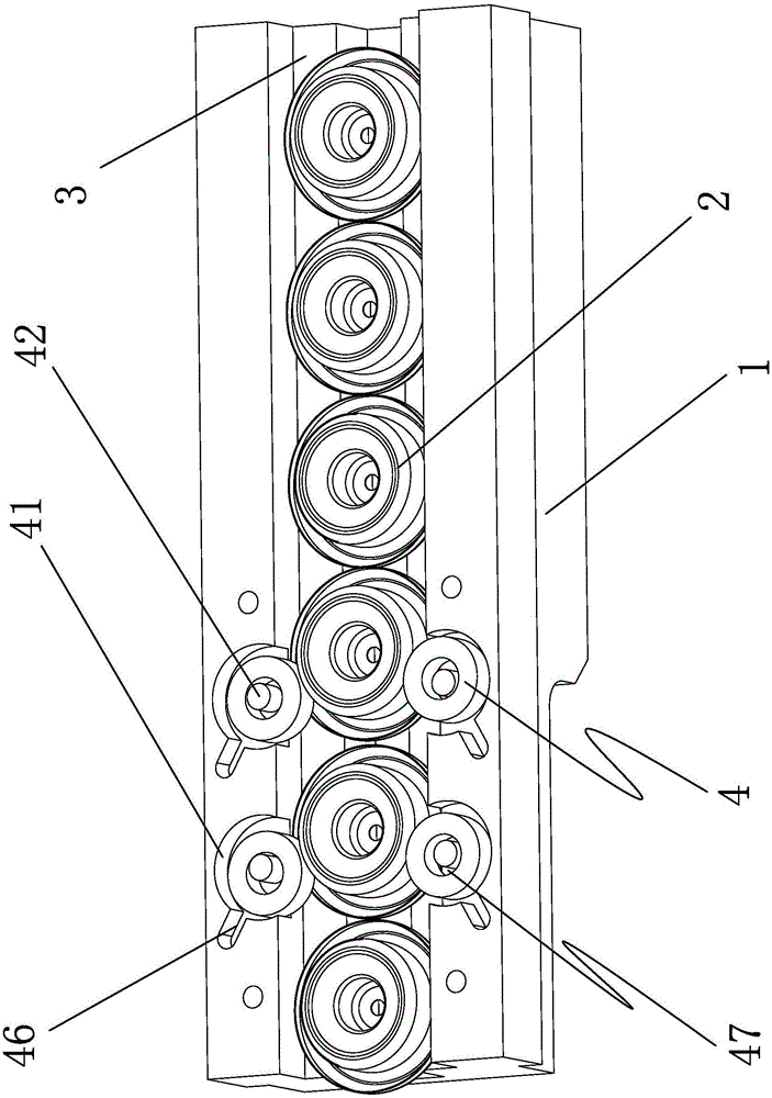
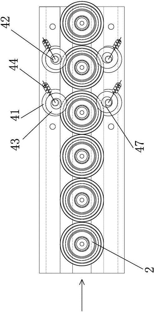
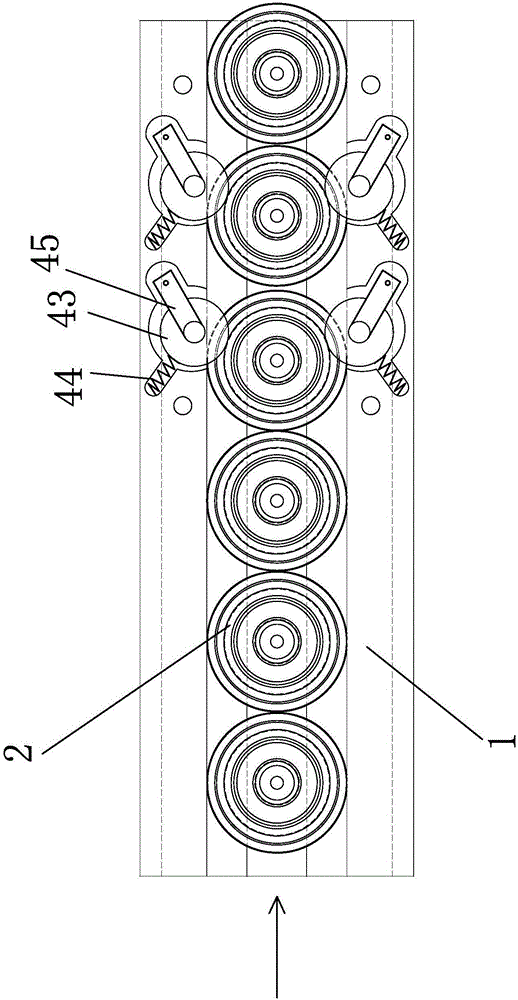
[0023] The first embodiment of the movable roller mechanism 4 in the present invention includes a mounting groove 41 arranged on the track seat 1, a pin shaft 42 is arranged in the mounting groove 41, and a There is a roller 43 that can swing relative to the pin shaft 42 , and an elastic member 44 that can push the roller 43 to the material 2 is arranged in the installation groove 41 .

[0024] The second embodiment of the movable roller mechanism 4 described in the present invention includes a mounting groove 41 arranged on the track seat 1, a swing arm 45 is arranged in the mounting groove 41, and one end of the swing arm 45 is connected to the mounting In the groove 41 , a roller 43 is arranged on the other end of the swing arm 45 , and an elastic member 44 capable of pushing the roller 43 to the material 2 is arranged in the installation groove 41 .

[0025] In the present invention, the track seat 1 is provided with a connection groove 46 communicating with the installati...


PUM


Abstract

The invention discloses a rail device with a material positioning mechanism. The rail device comprises a rail base, and a rail groove used for accommodating a material is arranged in the rail base. The rail device is characterized in that active roller mechanisms capable of stopping the material from moving forward in the rail groove are arranged on the rail base. The rail device provided by the invention aims to overcome defects in the prior art, and is simple in structure, convenient to use and mount, and good in positioning effect. By adoption of the rail device, the material can be prevented from being scratched, and the impact on the passing of follow-up materials through the rail device can be avoided.

Description

technical field [0001] The invention relates to a track device with a material positioning mechanism. Background technique [0002] At present, in the production process of emulsion pumps and spray valves, the materials produced in each process need to be transported to the next process through rails. There are often positioning mechanisms in the rails. The existing positioning mechanisms are relatively complicated in structure and easy to scratch. material or obstruct the passage of subsequent material. This will affect normal production work, increase equipment failures, and reduce production efficiency. [0003] Therefore, the existing track device with a material positioning mechanism needs to be further improved. Contents of the invention [0004] The purpose of the present invention is to overcome the deficiencies in the prior art and provide a material positioning mechanism with simple structure, convenient use, convenient installation, good positioning effect, no...

Claims


Application Information

Patent Timeline
Patent Type & Authority Applications(China)
IPC IPC(8): B65G47/88
CPCB65G47/8876B65G2205/06
Inventor 马文超
Owner ZHONGSHAN MEIJIESHI PACKAGING PROD
Learn More