Cylinder head cleaning machine

A cleaning machine and cylinder head technology, applied in the field of cleaning machines, can solve problems such as low work efficiency, affecting manufacturing quality, and poor cleaning effect

Active Publication Date: 2014-11-26
CHONGQING KEBEN TECH
View PDF6 Cites 17 Cited by
  • Summary
  • Abstract
  • Description
  • Claims
  • Application Information

AI Technical Summary

Problems solved by technology

At present, because there is no special cleaning equipment, manual methods have been used for cleaning. Not only the labor intensity o

Method used


Image

  • Cylinder head cleaning machine
  • Cylinder head cleaning machine
  • Cylinder head cleaning machine

Examples


Embodiment Construction

[0054]Embodiments of the present invention are described below through specific examples, and those skilled in the art can easily understand other advantages and effects of the present invention from the content disclosed in this specification. The present invention can also be implemented or applied through other different specific implementation modes, and various modifications or changes can be made to the details in this specification based on different viewpoints and applications without departing from the spirit of the present invention.

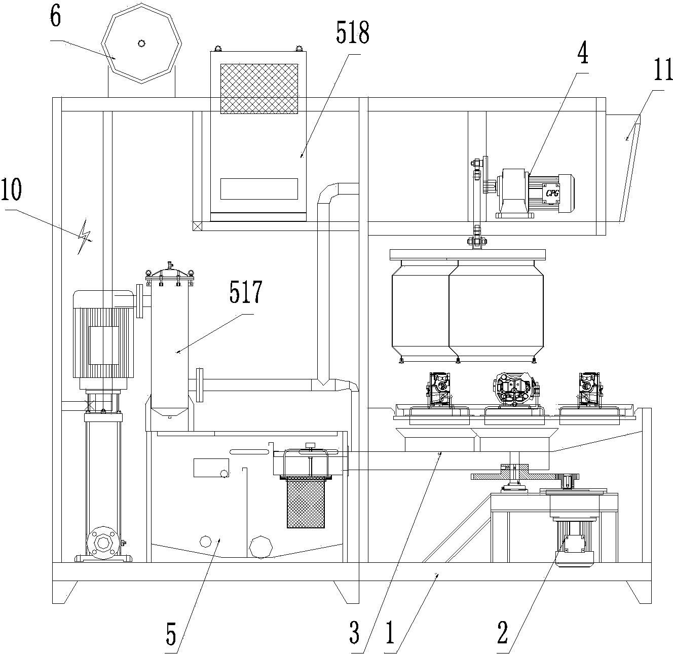
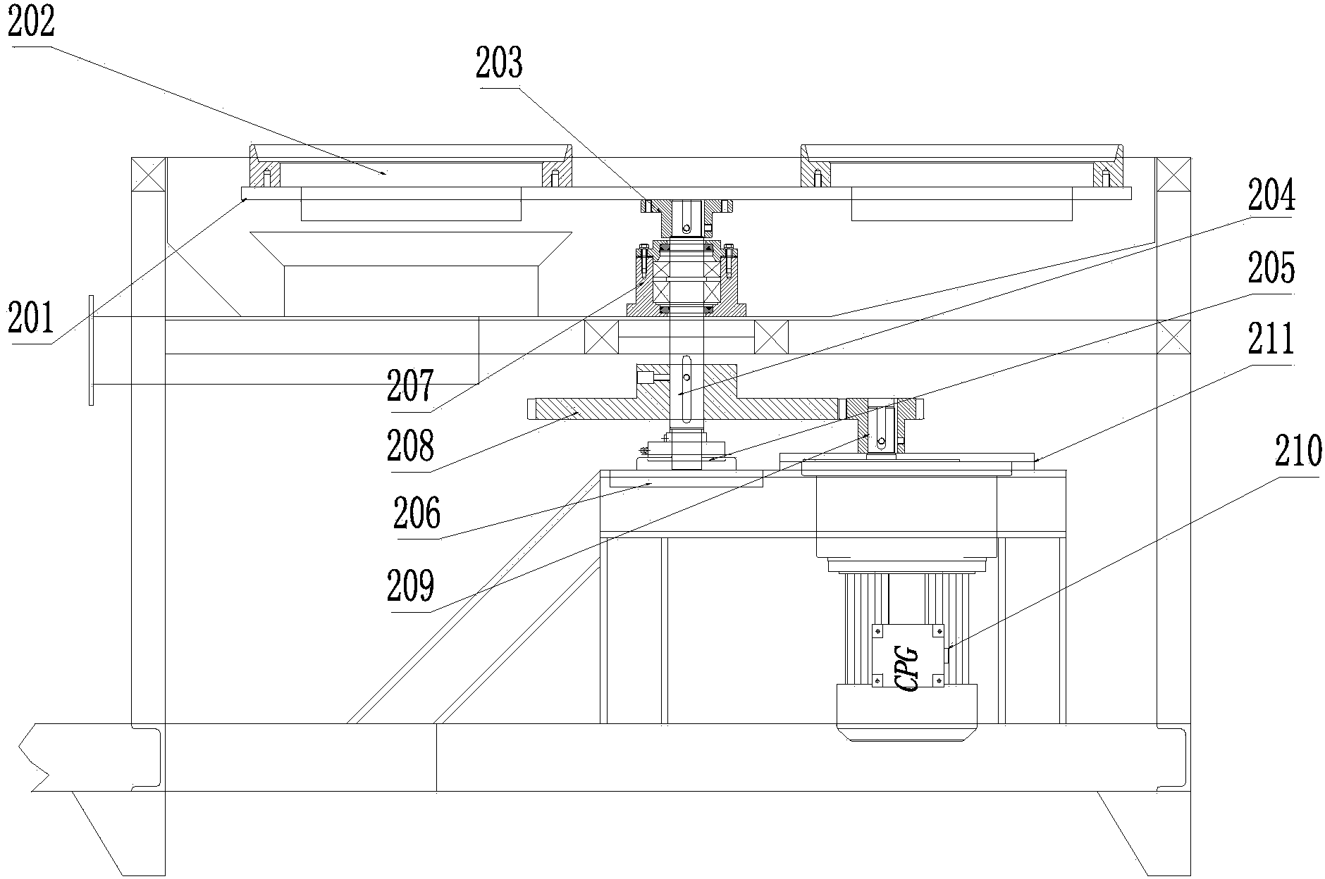
[0055] According to attached figure 1 , 2 As shown, a cylinder head cleaning machine includes a frame 1. The front of the frame 1 is a workbench. The workbench is supported by a rotating mechanism 2 and drives the workbench to rotate. A water receiving tank 3 is provided below the workbench. There are spray components and wind shear components above and below the workbench. The upper spray component and wind shear components are set i...


PUM


Abstract

The invention provides a cylinder head cleaning machine which comprises a machine frame. A working table is arranged at the front of the machine frame and supported by a rotating mechanism, the rotating mechanism drives the working table to rotate, the upper portion of the working table is provided with a spray assembly and a wind cutting assembly, the lower portion of the working table is also provided with a spray assembly and a wind cutting assembly, the spray assembly and the wind cutting assembly which are located on the upper portion are arranged in a lifting mechanism and driven to move upwards and downwards through the lifting mechanism, the spray assemblies are connected with a liquid storage tank, a water receiving tank is further arranged below the working table and connected with the liquid storage tank, the wind cutting assemblies are connected with an air storage tank, and the liquid storage tank is connected with the spray assemblies through a bag filter and a spray cleaning pump or a spray rinsing pump. The cylinder head cleaning machine further comprises a main control cabinet arranged on the rear portion of the machine frame and an operation panel arranged above the working table.

Description

technical field [0001] The invention relates to a washing machine, in particular to a motorcycle cylinder head washing machine. Background technique [0002] After the motorcycle cylinder head is processed, it is necessary to clean the inner and outer surfaces of the cylinder head and its concave structure, so as to remove the residual dust, iron filings, oil stains, etc. on the inner surface. At present, because there is no special cleaning equipment, manual methods have been used for cleaning. Not only the labor intensity of workers is high, the work efficiency is low, but also the cleaning effect is poor, which directly affects the manufacturing quality. Contents of the invention [0003] In view of the deficiencies in the prior art, the invention provides a cylinder head cleaning machine. [0004] A cylinder head cleaning machine, including a frame, the front of the frame is a workbench, the workbench is supported by a rotating mechanism, and drives the workbench to r...

Claims


Application Information

Patent Timeline
IPC IPC(8): B08B3/02F26B21/00
CPCB08B3/024F26B21/004
Inventor 朱兴德余虹江刘建晏增盛
Owner CHONGQING KEBEN TECH
Why Eureka
Try Eureka