
Powder metallurgy synchronizer gear hub

A technology of powder metallurgy and synchronizer, which is applied to clutches, components with teeth, mechanically driven clutches, etc., can solve the problems of debris generation, easy to be crushed and damaged, and easy to produce deflection, etc., to achieve the elimination of debris, The effect of avoiding crushing damage and smoothly transmitting power and torque

Active Publication Date: 2016-06-22
NINGBO SHANGZHONGXIA AUTOMATIC TRANSMISSION
View PDF7 Cites 4 Cited by
  • Summary
  • Abstract
  • Description
  • Claims
  • Application Information

AI Technical Summary

Problems solved by technology

[0004] The purpose of the present invention is to solve the problem that the internal spline of the synchronizer hub and the external spline of the drive shaft are prone to deflection and the teeth of the internal spline at the press-in end of the synchronizer hub exist when the existing synchronizer is assembled. In order to solve the problem that the thick side is easily damaged by extrusion cutting and generate debris, a powder metallurgy synchronizer hub is provided, which can ensure that it is automatically kept coaxial with the external spline of the transmission shaft when it is installed on the external spline of the transmission shaft, And it can effectively avoid the crushing and shearing damage of the tooth thickness side of the spline in the press-in end of the synchronizer gear hub, and at the same time, it can transmit power and torque smoothly

Method used


Image

  • Powder metallurgy synchronizer gear hub
  • Powder metallurgy synchronizer gear hub
  • Powder metallurgy synchronizer gear hub

Examples


Embodiment 1

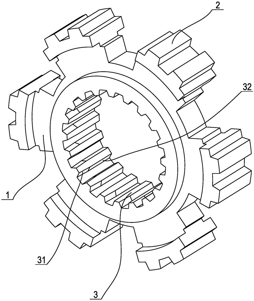
[0025] Embodiment 1: as figure 1 As shown, a powder metallurgy synchronizer hub includes a hub body 1, on the outside of the hub body 1 there is an outer spline 2 of the hub that meshes with the connecting sleeve in the synchronizer, and on the inside of the hub body there is a transmission The external splines of the shaft engage the internal splines of the gear hub 3. When assembling the synchronizer, the synchronizer gear hub is coaxially sleeved on the transmission shaft in a fixed direction and pressed into the external spline of the transmission shaft. When the synchronizer gear hub is assembled, it is first close to the drive shaft One end of the external spline becomes the press-in end. At this time, the internal spline 3 of the synchronizer hub forms a tight fit with the external spline on the transmission shaft, that is to say, the internal spline 3 of the gear hub and the external spline on the transmission shaft The external splines of the external splines cannot ...

Embodiment 2

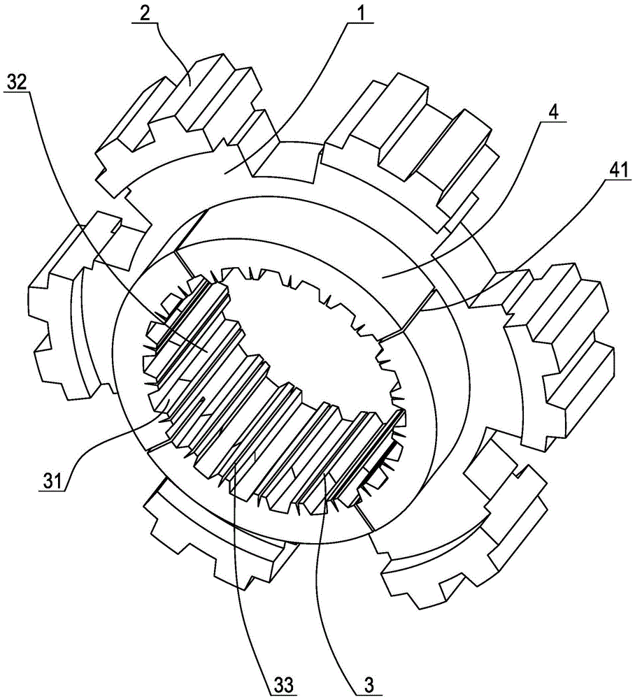
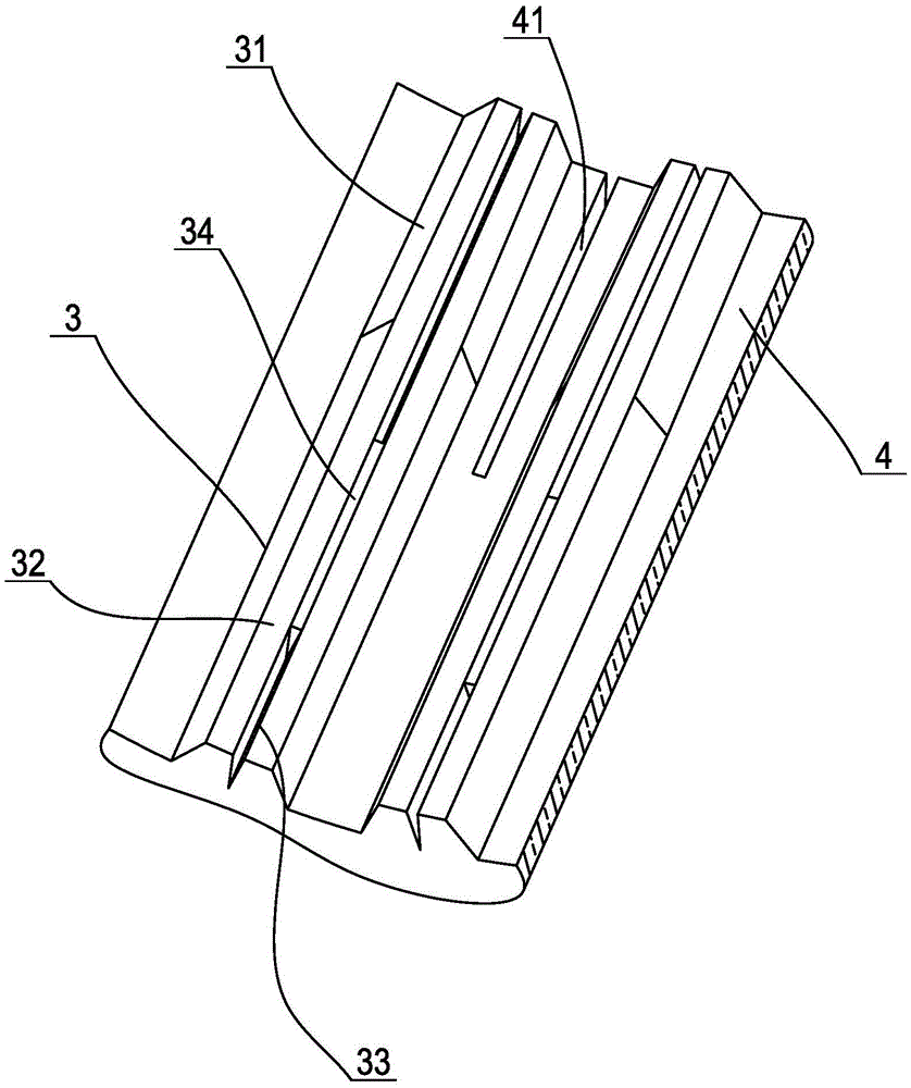
[0031] Embodiment 2: as Figure 4 As shown, a powder metallurgy synchronizer hub includes a hub body 1, on the outside of the hub body 1 there is an outer spline 2 of the hub that meshes with the connecting sleeve in the synchronizer, and on the inside of the hub body there is a transmission The external splines of the shaft engage the internal splines of the gear hub 3. In order to enable the synchronizer hub to transmit power and torque to the transmission shaft stably and reliably, the inner spline 3 of the gear hub includes a guide section 31 close to the press-in end of the synchronizer hub and a positioning section 32 away from the press-in end of the synchronizer hub. The teeth of the spline 3 in the gear hub are composed of transmission teeth 35 and 2-4 positioning teeth 36 equidistantly arranged between the transmission teeth 35 . The indexing round tooth thickness of each positioning spline 36 in the positioning section 32 is less than the indexing round tooth groov...


PUM


Abstract

The invention discloses a powder metallurgy synchronizer gear hub which comprises a gear hub body, an outer gear hub spline on the outer side of the gear hub body, and an inner gear hub spline on the inner side of the gear hub body. The inner gear hub spline comprises a guide section close to the press-in end of the synchronizer gear hub, and a locating section away from the press-in end of the synchronizer gear hub. The reference circle tooth thickness of the guide section is gradually increased from the press-in end of the synchronizer gear hub to the joint of the guide section and the locating section, and the reference circle tooth thickness of the guide section and the reference circle tooth thickness of the locating section are in smooth transition. The reference circle tooth thickness, at the press-in end of the synchronizer gear hub, of the guide section is smaller than the width of a reference circle tooth groove of an outer spline of a transmission shaft. It can be ensured that the powder metallurgy synchronizer gear hub is automatically kept coaxial with the outer spline of the transmission shaft when mounted on the outer spline of the transmission shaft, it is effectively avoided that the thick side faces of teeth of an inner spline at the press-in end of the synchronizer gear hub are extruded to be damaged, and meanwhile power and torque can be stably transferred.

Description

technical field [0001] The invention relates to a synchronizer in an automobile transmission, in particular to a synchronizer hub made of powder metallurgy in the synchronizer. Background technique [0002] In the transmission of an automobile, the function of the synchronizer is a device that synchronizes the speed of the gears that are engaged with each other when shifting gears. We know that in the process of shifting gears, the peripheral speeds of the mating ring gears of the pair of gears to be meshed should be equal, so that the gear can be smoothly engaged, otherwise, there will be impacts between the two gear rings and noise will affect the gears. lifespan. In order to facilitate gear shifting, the automobile transmission is equipped with a synchronizer between the commonly used gears, so that a pair of gears that are meshing are synchronized first and then meshed. Synchronizers have normal pressure type and inertial type. At present, inertial synchronizers are mo...

Claims


Application Information

Patent Timeline
Patent Type & Authority Applications(China)
IPC IPC(8): F16D23/04F16H55/17
CPCF16D23/04F16D2023/0625F16D2023/0656F16H55/17F16H2055/176
Inventor 倪良军宋伟郭跃灵罗大国陈勇王瑞平
Owner NINGBO SHANGZHONGXIA AUTOMATIC TRANSMISSION
Learn More