Throat liner machining equipment

A technology of processing equipment and throat lining, applied in the field of throat lining processing equipment, can solve the problems of easy damage to the outer surface of carbon rods, large spindle vibration, low production efficiency, etc., to avoid clamping damage, facilitate assembly and disassembly, and improve production efficiency effect

Inactive Publication Date: 2016-06-01
黄泗平 +2
View PDF7 Cites 0 Cited by
  • Summary
  • Abstract
  • Description
  • Claims
  • Application Information

AI Technical Summary

Problems solved by technology

[0002] Throat lining is the lining material of the throat of the solid rocket motor nozzle. There are multiple through holes inside it. When the rocket is launched, the gas is ejected through the throat of the nozzle to generate thrust. It has very high requirements; most of the throat lining materials currently used are carbon rods. During processing, due to the need to process more through holes on the carbon rods, the carbon rods need to be turned over manually. The production efficiency of the conventional clamping method is low. It is easy to damage the outer surface of the carbon rod and at the same time, the main shaft vibrates greatly when drilling holes, which may easily cause the drill bit to break and cause the product to be scrapped

Method used


Image

  • Throat liner machining equipment

Examples


Embodiment Construction

[0014] In order to make the purpose, technical solutions and advantages of the embodiments of the present invention clearer, a clear and complete description will be made below in conjunction with the technical solutions in the embodiments of the present invention. Obviously, the described embodiments are part of the embodiments of the present invention, and Not all examples. Based on the embodiments of the present invention, all other embodiments obtained by persons of ordinary skill in the art without making creative efforts belong to the protection scope of the present invention.

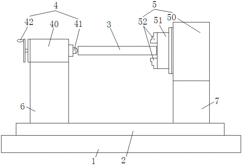
[0015] The throat liner processing equipment of the preferred embodiment of the present invention is as figure 1 As shown, it includes a CNC machine tool (not shown in the figure), and the CNC machine tool (not shown in the figure) includes a saddle 1, and the upper surface of the saddle 1 is provided with a backing plate 2 that can extend the upper surface of the saddle 1 and slide laterally. T...


PUM


Abstract

The invention relates to throat liner machining equipment. The throat liner machining equipment comprises a numerically-controlled machine tool, wherein the numerically-controlled machine tool comprises a saddle; a backing plate is arranged on the upper surface of the saddle; a first fixture and a second fixture are connected and arranged on the backing plate; the second fixture comprises a second fixed support seat; a rotating table is rotationally connected to one side facing the first fixture, of the second fixed support seat, and a clamping element is arranged on the rotating table; the first fixture comprises a first fixed support seat; an ejection rod capable of stretching out towards the direction of the second fixture to eject the end surface of one end departing from the second fixture, of a workpiece, is arranged on the first fixed support seat; during machining, one end of the workpiece is fixed on the clamping element, and the other end of the workpiece is tightly ejected through the ejection rod, thus vibration between a spindle of the numerically-controlled machine tool and the workpiece is reduced, and clamping damages to a drilling part of the workpiece are also avoided; and by using the numerically-controlled machine tool, accuracy during machining is ensured, in addition, the workpiece is driven to transversally move and rotate through the transversal movement carried out through the backing plate and the rotation of the rotating table, and accuracy control is facilitated, thus the production efficiency is improved.

Description

technical field [0001] The invention relates to the technical field of throat lining processing, and more specifically, relates to a throat lining processing equipment. Background technique [0002] Throat lining is the lining material of the throat of the solid rocket motor nozzle. There are multiple through holes inside it. When the rocket is launched, the gas is ejected through the throat of the nozzle to generate thrust. It has very high requirements; most of the throat lining materials currently used are carbon rods. During processing, due to the need to process more through holes on the carbon rods, the carbon rods need to be turned over manually. The production efficiency of the conventional clamping method is low. It is easy to damage the outer surface of the carbon rod, and at the same time, the main shaft vibrates greatly during drilling, which may easily cause the drill bit to break and cause the product to be scrapped. Contents of the invention [0003] The te...

Claims


Application Information

Patent Timeline
Patent Type & Authority Applications(China)
IPC IPC(8): B28D7/04B28D1/14
CPCB28D7/04B28D1/14
Inventor 黄泗平罗兴帮邹雪鸿
Owner 黄泗平
Why Eureka
Try Eureka