
Luminous intensity adjustment circuit and method thereof

A technology for luminous intensity and circuit adjustment, which is applied in the direction of electric lamp circuit layout, light source, electric light source, etc., can solve the problem of small AC components, achieve the effects of reducing power consumption and cost, enhancing signal range, and reducing noise

Active Publication Date: 2017-12-29
CHENGDU VCARE QINYUAN HEALTH TECH
View PDF4 Cites 0 Cited by
  • Summary
  • Abstract
  • Description
  • Claims
  • Application Information

AI Technical Summary

Problems solved by technology

[0002] Since the DC component of the physiological signal has a large dynamic range, but the AC component is very small, in order to identify the AC component, a high-precision ADC (usually above 18bit) is required, which causes great power consumption and cost overhead

Method used


Image

  • Luminous intensity adjustment circuit and method thereof
  • Luminous intensity adjustment circuit and method thereof

Examples


Embodiment Construction

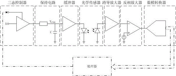
[0030] Describe technical scheme of the present invention in further detail below in conjunction with accompanying drawing: as figure 1 As shown, a luminous intensity adjustment circuit is characterized in that: it includes a three-state controller, a holding circuit, a buffer, an optical sensor, a transconductance amplifier, an inverting amplifier, an analog-to-digital converter and a processor; the three The signal input terminal of the state controller inputs a voltage or current pulse signal with a certain pulse width, the output terminal of the three-state controller is connected to the holding circuit, the output terminal of the holding circuit is connected to the buffer, and the output end of the buffer is connected to the optical sensor. The output terminal of the optical sensor is connected to the transconductance amplifier, the output terminal of the transconductance amplifier is connected to the inverting input terminal of the inverting amplifier, the output terminal...


PUM


Abstract

The invention discloses a luminous intensity adjusting circuit and a method thereof. The circuit comprises a tri-state controller, a holding circuit, a buffer, an optical sensor, a transconductance amplifier, an inverting amplifier, an analog-to-digital converter and a processor. A voltage / current pulse signal of a certain pulse width is input into the signal input end of the tri-state controller. The output end of the tri-state controller is connected with the holding circuit. The output end of the holding circuit is connected with the buffer. The output end of the buffer is connected with the optical sensor. The output end of the optical sensor is connected with the transconductance amplifier. The output end of the transconductance amplifier is connected with the inverting amplifier. The output end of the inverting amplifier is connected with the analog-to-digital converter. The output end of the analog-to-digital converter is connected with the processor. The output end of the processor is connected with the control input end of the tri-state controller. According to the technical scheme of the invention, through dynamically adjusting the luminous intensity, the DC component of a signal is fixed, so that only the AC component of the signal needs to be recognized. Therefore, the requirement on the ADC accuracy is greatly broadened. Meanwhile, the power consumption and the cost overhead are reduced.

Description

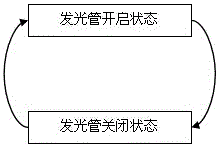
technical field [0001] The invention relates to a luminous intensity adjusting circuit and a method thereof. Background technique [0002] Since the DC component of the physiological signal has a large dynamic range, but the AC component is very small, in order to identify the AC component, a high-precision ADC (usually above 18bit) is required, which results in huge power consumption and cost overhead. [0003] The present invention fixes the DC component of the signal by dynamically adjusting the luminous intensity, and only needs to identify the AC component, which greatly relaxes the requirement for ADC precision and reduces power consumption and cost. Since the signal received by the receiving tube is determined by the luminous intensity and the signal itself, as the DC component of the signal changes, the luminous intensity is dynamically adjusted so that the DC component in the signal received by the receiving tube remains constant; otherwise, due to the high sensitiv...

Claims


Application Information

Patent Timeline
Patent Type & Authority Patents(China)
IPC IPC(8): H05B37/02
CPCH05B47/10
Inventor 崔予红
Owner CHENGDU VCARE QINYUAN HEALTH TECH
Learn More