Pneumatic punching-riveting device

A punching riveting and pneumatic technology, applied in the field of stamping, can solve problems such as complicated device operation, unreliable punching riveting quality, oil leakage, etc., and achieve the effect of convenient operation, simple structure and easy use

Active Publication Date: 2016-06-29
HUBEI SANJIANG AEROSPACE HONGFENG CONTROL
View PDF6 Cites 0 Cited by
  • Summary
  • Abstract
  • Description
  • Claims
  • Application Information

AI Technical Summary

Problems solved by technology

The traditional punching riveting machine mostly adopts a hydraulic structure, and its oil pipes, joints, hydraulic pumps, and reversing valves are prone to oil leakage
It will cause unreliable punching riveting quality, which will affect product quality and reliability
Most of the existing pneumatic riveting devices are single-directional punching riveting operations, that is, performing single-directional punching riveting operations on the workpiece, and the operation of the device is relatively complicated
None of the above riveting devices can meet the actual needs

Method used


Image

  • Pneumatic punching-riveting device
  • Pneumatic punching-riveting device
  • Pneumatic punching-riveting device

Examples


Embodiment Construction

[0027] In order to make the object, technical solution and advantages of the present invention clearer, the present invention will be further described in detail below in conjunction with the accompanying drawings and embodiments. It should be understood that the specific embodiments described here are only used to explain the present invention, not to limit the present invention. In addition, the technical features involved in the various embodiments of the present invention described below can be combined with each other as long as they do not constitute a conflict with each other.

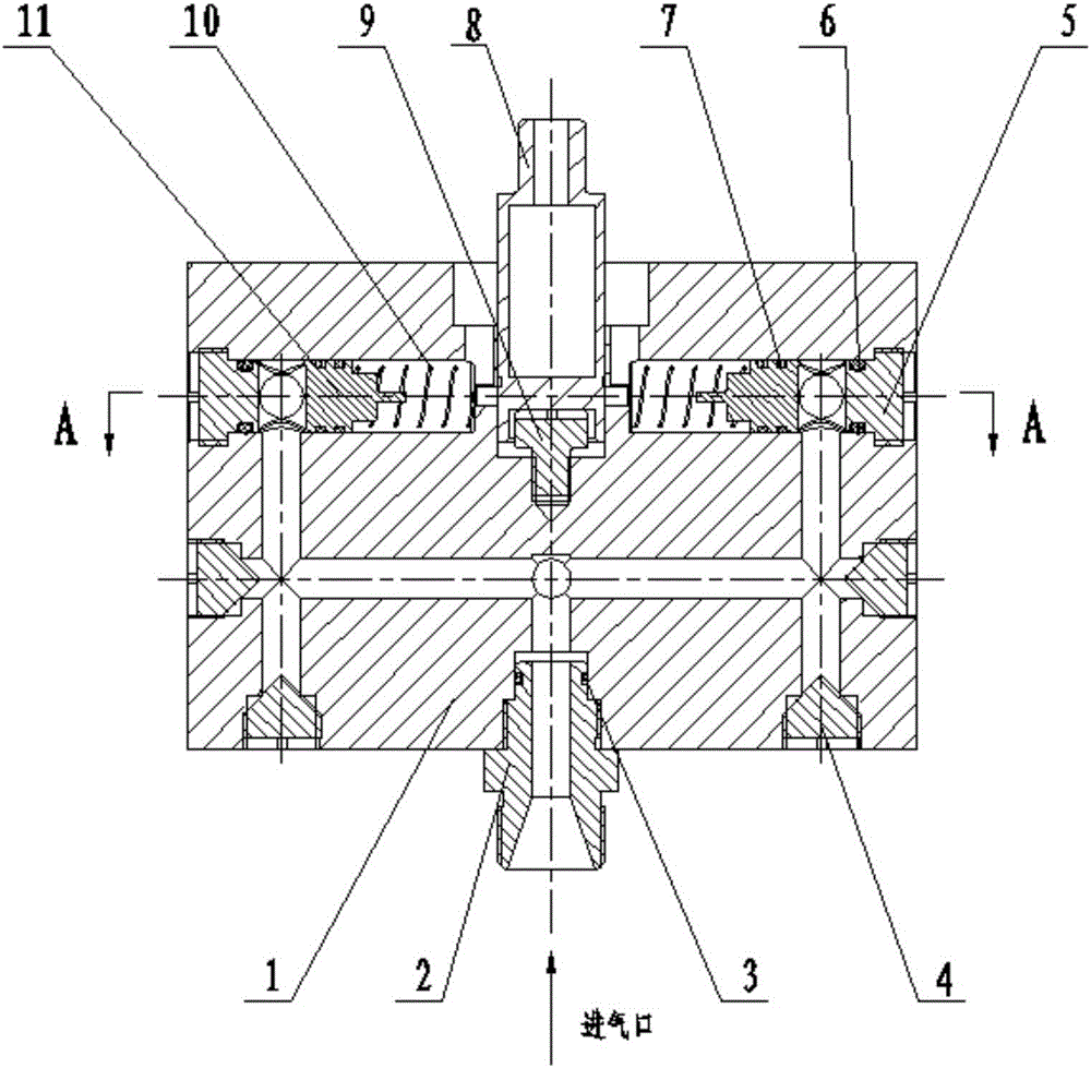
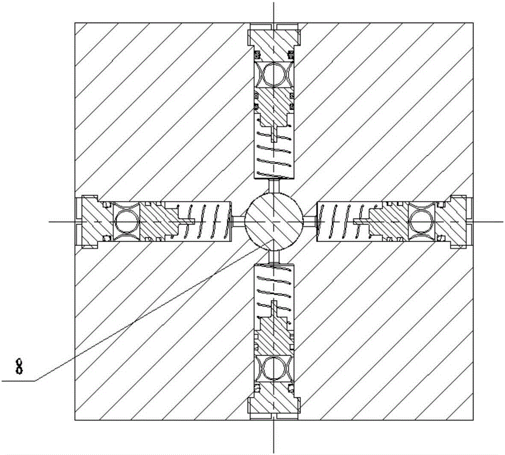
[0028] figure 1 It is a schematic diagram of the internal structure of the pneumatic punching riveting device in the embodiment of the present invention, figure 2 yes figure 1 Middle A-A internal sectional view, it can be seen from the figure that in the pneumatic riveting device of the present invention, the plug 4 and the body 1 are connected by threads, and the plug 4 and the body 1 are se...


PUM


Abstract

The invention discloses a pneumatic punching-riveting device and relates to the technical field of punching. The pneumatic punching-riveting device comprises a body, pistons, springs and an adjusting screw; a station containing a work-piece to be punched and riveted is arranged in the body, and the adjusting screw is arranged on the bottom of the station for vertically adjusting the position of the work-piece to be punched and riveted from the bottom; guide grooves are formed in the body, the pistons and the springs are arranged inside the guide grooves, the pistons face the position to be punched and riveted of the work-piece to be punched and riveted, and the springs are arranged at the front ends of the pistons and are used for enabling the pistons completing the punching-riveting work to be reset; air channels are formed in the body and communicate with the guide grooves, and high-pressure gas in the air channels enter the guide grooves for impacting the pistons and enabling the pistons to execute the punching-riveting work. According to the device, use of hydraulic structures is avoided, and oil leakage is avoided. In addition, the pneumatic punching-riveting device is safe, reliable, simple in structure, convenient to operate, capable of carrying out the punching-riveting work in multiple directions and high in efficiency.

Description

technical field [0001] The invention relates to the technical field of stamping, in particular to a pneumatic riveting device, which is suitable for the multi-directional punching and riveting process of various workpieces. Background technique [0002] Pneumatic punching riveting device is a device that uses air pressure for punching riveting operations. The punching riveting process means that the workpiece is placed on the press, and the axial force is directly applied through the punch to make the material expand in the radial direction to achieve the purpose of plastic deformation. The traditional riveting machine mostly adopts hydraulic structure, and its oil pipes, joints, hydraulic pumps and reversing valves are prone to oil leakage. It will cause unreliable punching riveting quality, and then affect product quality reliability. Most of the existing pneumatic riveting devices are single-directional punching riveting operations, that is, performing single-directiona...

Claims


Application Information

Patent Timeline
Patent Type & Authority Applications(China)
IPC IPC(8): B21D39/00
CPCB21D39/00
Inventor 潘伟周华波王跃
Owner HUBEI SANJIANG AEROSPACE HONGFENG CONTROL
Why Eureka
Try Eureka