Rotating and positioning device of control cabin bracket

A technology of positioning device and operating room, which is applied in the directions of transportation and packaging, load hanging components, etc., to achieve the effects of easy installation, high positioning stability, and simple and easy assembly method.

Active Publication Date: 2016-06-29
XCMG CONSTR MACHINERY
View PDF4 Cites 0 Cited by
  • Summary
  • Abstract
  • Description
  • Claims
  • Application Information

AI Technical Summary

Problems solved by technology

[0007] The technical problem to be solved by the present invention is to increase the installation accuracy of the control room bracket and the turntable by adding a rotating positioning mechanism for the control room bracket and using bolt adjustment to precisely position the rotation angle of the control room bracket If the frame rotation angle is too large, the structural parts will collide with each other, thereby improving the installation efficiency and safety factor of the crawler crane

Method used


Image

  • Rotating and positioning device of control cabin bracket
  • Rotating and positioning device of control cabin bracket
  • Rotating and positioning device of control cabin bracket

Examples


Embodiment 1

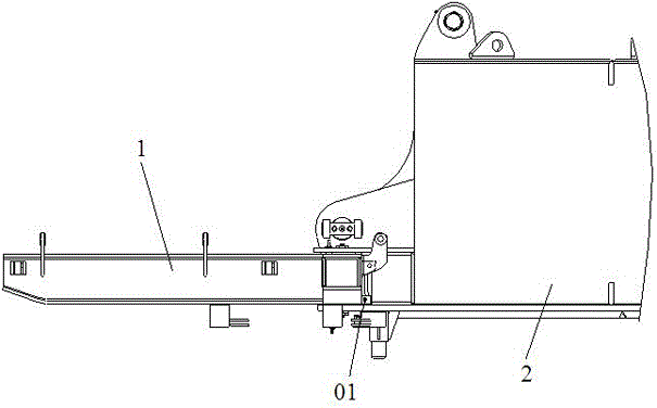
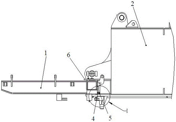
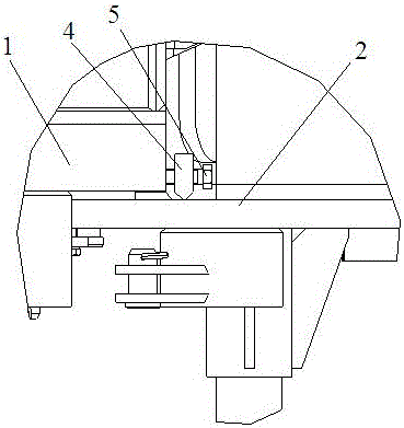
[0031] Such as Figure 2 to Figure 6 In the shown embodiment, the positioning plate 6 is arranged parallel to the upper surface of the control room bracket 1 , and the pin shaft 3 runs through the control room bracket 1 and the positioning plate 6 sequentially from bottom to top.

[0032] The positioning plate 6 is provided with 2 positioning holes 7, and the control room bracket 1 is provided with 1 positioning hole 7 adapted to the positioning holes 7 on the positioning plate 6, so that: when the control room bracket 1 is in the transport state 11 Or when the working state is 12, one of the positioning holes communicates with one of the positioning holes on the console bracket 1 on the positioning plate 6 .

[0033] The lower end of the nut plate 4 in the bolt positioning assembly is welded on the turntable 2; the head of the screw rod 5 faces the turntable 2, and the tail, ie, the end of the rod, faces the console 1 of the control room. The distance between the tail of the...

Embodiment 2

[0035] There are 2 positioning holes on the bracket of the control room, and 1 positioning hole on the positioning plate that is compatible with the positioning holes on the bracket of the control room, so that: when the bracket of the control room is in the transport state and working state, the positioning One positioning hole on the board communicates with two positioning holes on the console bracket respectively.

[0036] To sum up the above two embodiments, when the crane needs to be transported, the control room bracket is rotated to the transport state, so that the control room bracket is aligned with the positioning hole on the positioning plate, the positioning pin is inserted, and the bolt is tightened at the same time. The screw in the assembly makes the positioning of the cab bracket more secure. When it is necessary to assemble and then work, rotate the screw to leave a rotation gap for the control room bracket. After the control room bracket is rotated to the wor...


PUM


Abstract

The invention discloses a rotating and positioning device of a control cabin bracket. The rotating and positioning device of the control cabin bracket comprises a bolt positioning assembly and a positioning plate assembly. The control cabin bracket and a rotary table are assembled in a rotary connection mode through a pin shaft so that rotary switching between the transport state and the operation state can be completed conveniently. The bolt positioning assembly comprises a screw rod and a nut plate which are in threaded connection. The nut plate is fixedly connected with the rotary table, one end of the screw rod faces the rotary table, and the other end of the screw rod penetrates through the nut plate and faces the control cabin bracket. The positioning plate assembly comprises a positioning plate and a positioning pin. The positioning plate is fixedly connected with the pin shaft and the rotary table, and provided with more than one positioning hole. The control cabin bracket is provided with more than one positioning hole adapting to the positioning holes in the positioning plate. In this way, when the control cabin bracket is in the transport state or the operation state, one of the positioning holes in the positioning plate communicates with the corresponding positioning hole in the control cabin bracket all the time, and then the positioning pin is plugged into the positioning holes for positioning. The rotating angle of the control cabin bracket is positioned accurately through bolt adjustment, and meanwhile the positioning plate assembly is used in cooperation for positioning, so that the mounting accuracy of the control cabin bracket and the rotary table is improved.

Description

technical field [0001] The invention relates to the technical field of crawler crane design, in particular to a rotary positioning device for a control room bracket of a crawler crane. Background technique [0002] Related terms: [0003] 1) Crawler crane: a crane with a truss-type jib structure using a crawler chassis; [0004] 2) Control room bracket: a device that installs the control room and can be rotated. [0005] During the installation, transportation or working process of the crawler crane, the transport width and working state of the main engine will be changed by rotating the bracket of the control room. There are two installation states between the bracket of the control room and the turntable. Through the rotation and installation of the bracket of the control room Fixing of positioning holes to achieve different states. Due to the large rotation angle range of the control room bracket, it is not easy to ensure the coaxiality of the positioning holes on the ...

Claims


Application Information

Patent Timeline
Patent Type & Authority Applications(China)
IPC IPC(8): B66C13/54
CPCB66C13/54
Inventor 孟朝钰李聪李炳田
Owner XCMG CONSTR MACHINERY
Why Eureka
Try Eureka