A vibration isolation system with controllable stiffness damping and inertia force and its control method

A vibration isolation system, inertial force technology, applied in inertial force compensation, vibration suppression adjustment, non-rotation vibration suppression and other directions, can solve problems such as unsatisfactory vibration reduction effect

Inactive Publication Date: 2018-01-16
JIANGSU UNIV
View PDF7 Cites 0 Cited by
  • Summary
  • Abstract
  • Description
  • Claims
  • Application Information

AI Technical Summary

Problems solved by technology

[0005] Most of the current vibration isolation equipment control methods only involve one variable among various parameters, which limits the maximum vibration reduction effect of the vibration isolation equipment, and the equipment cannot be in the best matching state of parameters at any instant, especially when the equipment is vibrating When the input frequency is changing, the vibration reduction effect will be even more unsatisfactory

Method used


Image

  • A vibration isolation system with controllable stiffness damping and inertia force and its control method
  • A vibration isolation system with controllable stiffness damping and inertia force and its control method
  • A vibration isolation system with controllable stiffness damping and inertia force and its control method

Examples


Embodiment Construction

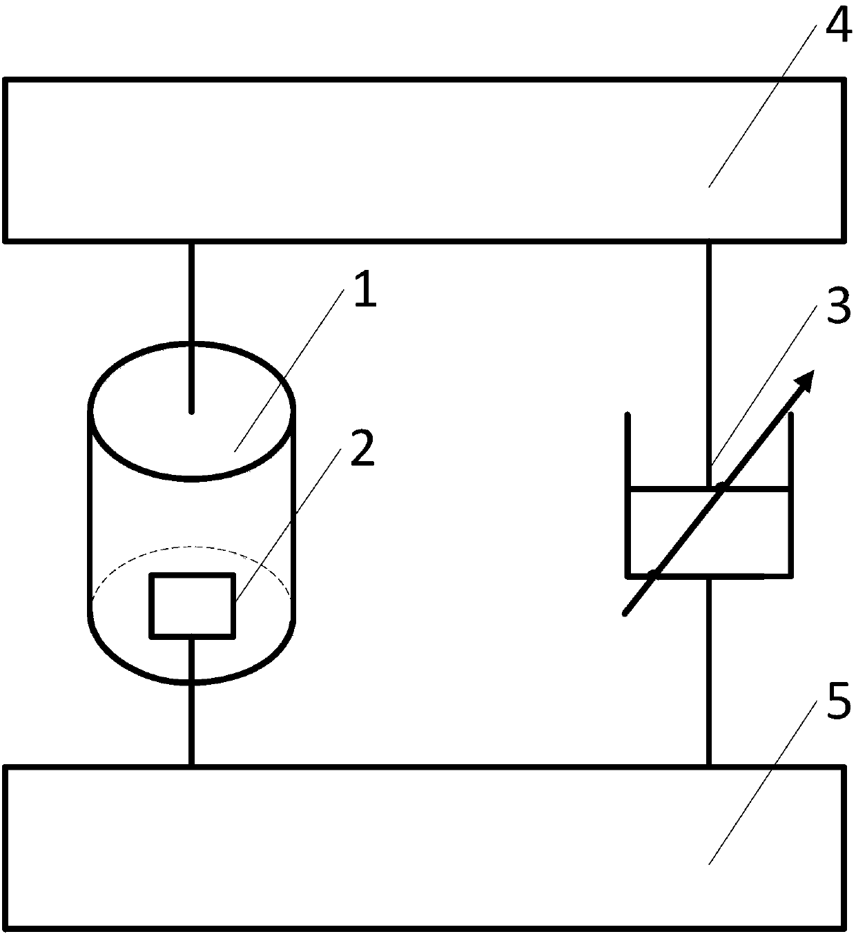
[0040] A vibration isolation system with controllable stiffness damping and inertia force, including a vibration isolation device and a control module;

[0041] In the vibration isolation device, an air spring 1, an inertial force generator 2, and a magnetorheological damper 3 are included; the inertial force generator 2 is placed in the air spring 1;

[0042] The air spring 1 is connected in parallel with the magneto-rheological damper 3; one end of the air spring 1 is connected to the vibrating mechanical equipment 4, and the other end of the air spring 1 is connected to the fixture 5; the magneto-rheological damper 3 One end is connected to the vibrating mechanical equipment 4, and the other end of the magneto-rheological damper 3 is connected to the fixture 5;

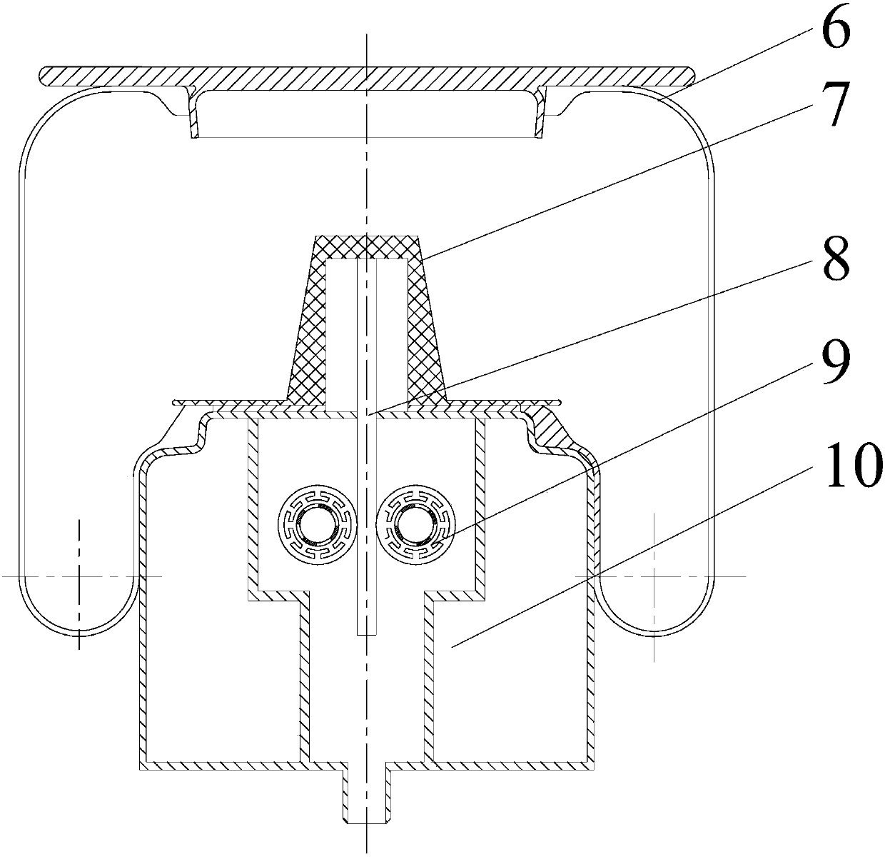
[0043] The air spring 1 includes an air spring body 6 and an air spring base 10; the air spring base 10 is placed in the center of the lower end of the air spring body 6, and the air spring body 6 and the air sprin...


PUM


Abstract

The invention provides a vibration isolation system with controllable rigid damping and inertia force and a control method of the vibration isolation system. The vibration isolation system comprises a vibration isolation device and a control module. The vibration isolation device comprises an air spring, an inertia force generator and a magneto-rheological type damper. The inertia force generator is arranged in the air spring. The control module comprises an information collection module, a computer module and a vibration isolation device control module. The information collection module comprises various sensors. The output end of the collection module is connected with AD conversion. The AD conversion is connected with input of the computer module. The output of the computer module is connected with the vibration isolation device control module. The signal collection module can directly or indirectly obtain the device working condition and transmit the device working condition to the computer module to be processed. The computer module sends an instruction to the vibration isolation device control module on the basis of the device working condition so as to control parameter adjustment of the vibration isolation device control module. Three vibration isolation parameters are changed at the same time, the negative effect of vibration is reduced to minimum, precision of vibration devices can be remarkably improved, and the service life of the vibration devices can be remarkably prolonged.

Description

technical field [0001] The invention belongs to the field of mechanical force control and its control method, especially the field of force control equipment using dynamic vibration absorption. The invention relates to a vibration isolation system and a control method thereof, in particular to a vibration isolation system with controllable stiffness damping and inertia force and a control method thereof. Background technique [0002] Mechanical equipment will inevitably vibrate during the working process. The vibration problem of the high-speed operation of the machine is a relatively prominent and difficult problem to solve. For equipment with complex structures, the vibration problem cannot be solved only by optimizing the design. Therefore, The vibration isolation device is an indispensable mechanical equipment, and the vibration isolation device can be used in many fields, such as vibration isolation in vehicles, buildings, bridges and other fields. The vibration isolat...

Claims


Application Information

Patent Timeline
Patent Type & Authority Patents(China)
IPC IPC(8): F16F13/00F16F15/00F16F15/023F16F15/027F16F15/22F16F9/53B60G17/06B60G17/052B60G17/015
CPCB60G17/015B60G17/052B60G17/06F16F9/535F16F13/002F16F15/002F16F15/0232F16F15/0275F16F15/22F16F2222/08F16F2222/12F16F2222/126
Inventor 陈龙刘昌宁杨晓峰刘雁玲沈钰杰
Owner JIANGSU UNIV
Why Eureka
Try Eureka