
Composite cover structure

A composite and cover technology, which is applied in the fields of instruments, computing, electrical digital data processing, etc., can solve the problem of low machinability

Active Publication Date: 2018-12-25
TPK TOUCH SOLUTIONS (XIAMEN) INC
View PDF4 Cites 0 Cited by
  • Summary
  • Abstract
  • Description
  • Claims
  • Application Information

AI Technical Summary

Problems solved by technology

As the protective outer cover of the touch panel, the cover plate must have sufficient strength, which requires the cover plate to have a certain thickness, usually 0.5-0.7 mm, and avoid opening or digging holes to cause strength damage. In this way, The space available for the cover plate to be used for touch panel processing and design is limited, and the processability is low, and this situation is not in line with the market trend of pursuing diversification of electronic products

Method used


Image

  • Composite cover structure
  • Composite cover structure
  • Composite cover structure

Examples


Embodiment Construction

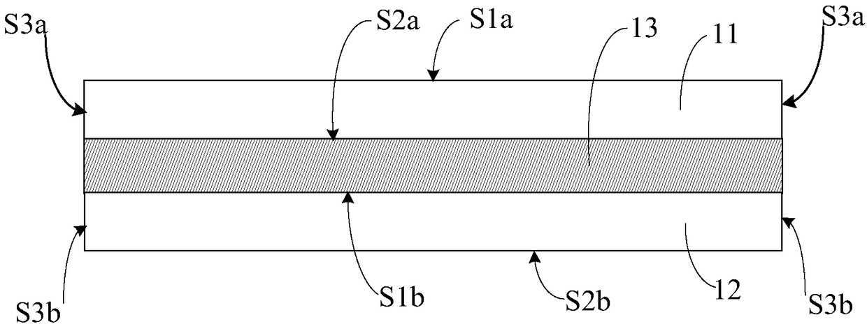
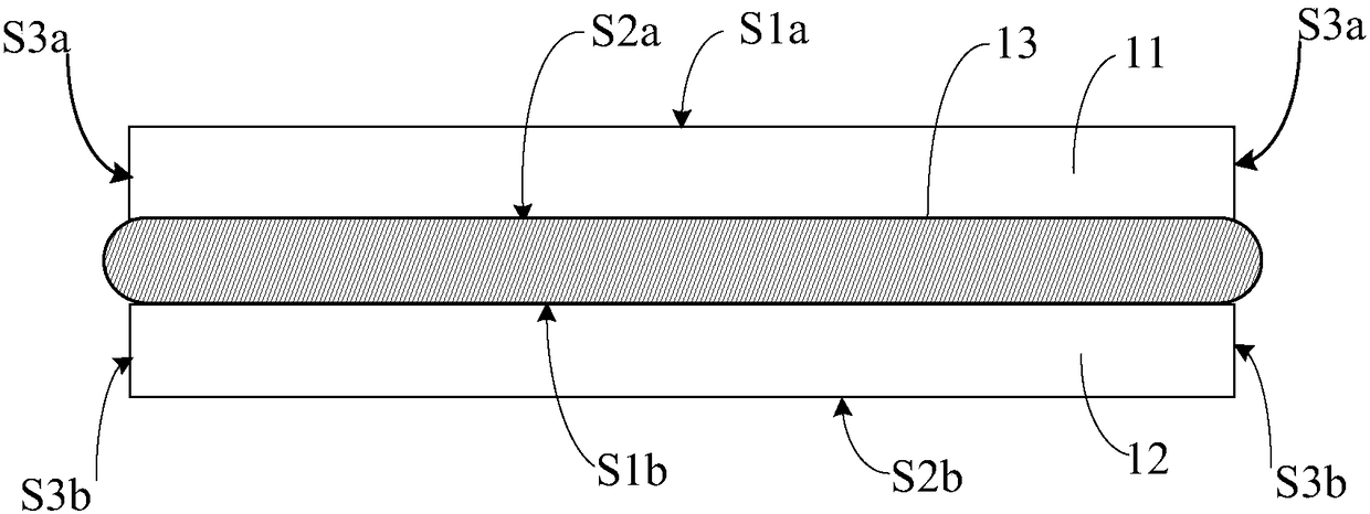
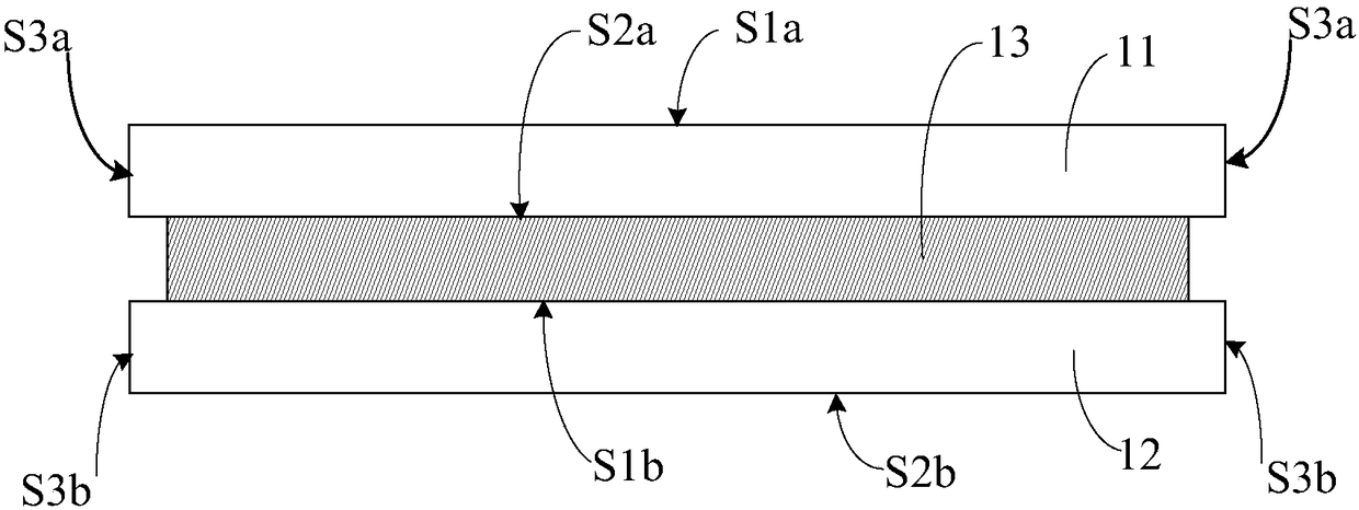
[0016] The present invention will be further described in detail below in conjunction with the accompanying drawings and specific embodiments. The aforementioned and other technical contents, features and functions of the present invention will be clearly presented in the following detailed description of two embodiments with reference to the drawings.

[0017] Here, it is worth noting that the orientations “up” and “down” mentioned in the detailed description of the embodiments of the present invention are only used to represent relative positional relationships. Figure 1A Of Figure 16 As far as the schematic diagram is concerned, the upper part is closer to the user, while the lower part is farther away from the user, but these descriptions about the orientation should not be used to limit the embodiments of the present invention. In addition, before the present invention is described in detail, it should be noted that in the following description, similar components are ...


PUM


Abstract

The invention discloses a composite cover plate structure. The structure comprises a first cover plate which is equipped with an upper surface and a lower surface, and an outer side surface between the upper surface and the lower surface, wherein the upper surface and the lower surface are opposite; a second cover plate which is equipped with an upper surface and a lower surface, and an outer side surface between the upper surface and the lower surface, wherein the upper surface and the lower surface are opposite, and the second cover plate is equipped with an opening; a first joint layer which is located between the lower surface of the first cover plate and the upper surface of the second cover plate; strengthening glue which at least covers the outer side surface of the first joint layer and parts of the outer side surface of the first cover plate and the outer side surface of the second cover plate; a fingerprint identification module which is arranged in the opening of the second cover plate; and a diamond-like carbon layer which is arranged on the first cover plate. According to the composite cover plate structure provided by the embodiment of the invention, under a condition of improving the integral strength and the anti-impact capability of the cover plate, the fingerprint identification function and the anti-scratch and anti-wear effects are increased.

Description

technical field [0001] The invention relates to a composite cover structure, in particular to a composite cover structure applied to a touch panel. Background technique [0002] With the development of technology, touch panels have been widely used in various consumer electronic devices, such as: smart phones, tablet computers, cameras, e-books, MP3 players and other portable electronic products, or used in Operate the display screen of the control device. [0003] A common touch panel usually includes at least one cover plate. The upper surface of the cover plate provides the touch operation of the touch object, and its lower surface can be bonded with a substrate with a touch-sensitive structure to form a touch panel. It can also be used on the cover plate The lower surface of the touch sensing structure is directly formed to form a monolithic glass integrated touch panel. As the protective outer cover of the touch panel, the cover plate must have sufficient strength, wh...

Claims


Application Information

Patent Timeline
Patent Type & Authority Patents(China)
IPC IPC(8): G06F3/041
Inventor 许毅中徐国书张春勇吴宇川黄邦熊陈炳辉贾瑞禹杨河波张羽叶惠林郑益良黄仕游
Owner TPK TOUCH SOLUTIONS (XIAMEN) INC
Learn More