A Method of Tooth End Modification and Parametric Modeling of Involute Straight Bevel Gears

A straight-toothed bevel gear, parametric modeling technology, applied in 3D modeling, image data processing, design optimization/simulation, etc., to improve gear load distribution and stress concentration, reduce vibration and noise levels, and improve transmission accuracy Effect

Active Publication Date: 2019-05-24
WUHAN UNIV OF TECH
View PDF5 Cites 0 Cited by
  • Summary
  • Abstract
  • Description
  • Claims
  • Application Information

AI Technical Summary

Problems solved by technology

Publication No. CN101937211A adopts the tooth profile and tooth direction modification method to modify the shape of the involute straight bevel gear, and adopts the dynamic finite element simulation method to determine the modification amount of the tooth profile of the large end of the bevel gear. It is a more reasonable method to make a modified profile on the center section of the tooth, and stretch the modified profile to the tooth surface equidistantly to realize the modeling process of the tooth-wise equidistant modified gear, and finally realize the modified gear processing by CNC machine tools. The modified gear processing method, but its disadvantage is that it can only realize the equidistant modification of the tooth direction, and cannot perform parametric modification according to actual needs, and change the modification parameters

Method used


Image

  • A Method of Tooth End Modification and Parametric Modeling of Involute Straight Bevel Gears
  • A Method of Tooth End Modification and Parametric Modeling of Involute Straight Bevel Gears
  • A Method of Tooth End Modification and Parametric Modeling of Involute Straight Bevel Gears

Examples


Embodiment Construction

[0035] In order to have a clearer understanding of the technical features, purposes and effects of the present invention, the specific implementation manners of the present invention will now be described in detail with reference to the accompanying drawings.

[0036] In the specific embodiment of the involute straight bevel gear tooth end modification and parametric modeling method of the present invention are as follows:

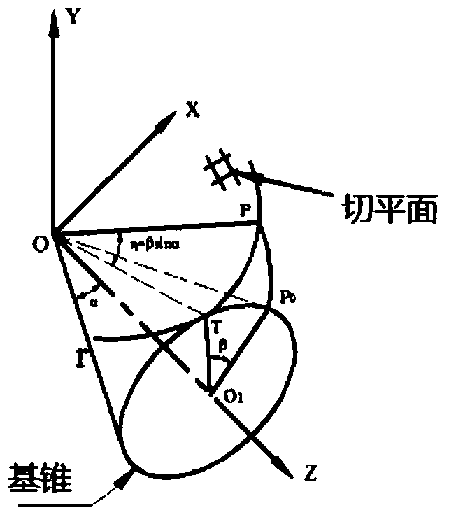
[0037] A point on the surface of the base cone, or a point on the surface of the subcone of the base circle rotates around the surface of the base cone to form a spherical involute. Such as figure 1 As shown, a point P on the tangent plane 0 The spherical involute PP is formed after rotating around the base cone surface by angle β 0 . Taking the large-end spherical involute as the starting line and the small-end spherical involute as the ending line, the standard unmodified spur bevel gear tooth surface can be obtained by using the variable section swee...


PUM


Abstract

The present invention relates to an involute straight tooth bevel gear tooth end correction and parameterized modeling method. The method comprises the following steps: S1, performing finite element analysis on an involute straight tooth bevel gear whole profile is not modified, so as to obtain a gear circumferential displacement difference of each key engaging position and a tooth surface equivalent touch stress distribution graph; S2, on the basis of the gear circumferential displacement difference, determining a profile modification amount of tooth end profile modification, and on the basis of the tooth surface equivalent touch stress distribution graph, determining a profile modification length; S3, by using the profile modification length and the profile modification amount as variables, establishing an equation of a tooth end profile modification curve and a profile modification tooth surface; and S4, according to the equation of the tooth profile modification curve and the profile modification tooth surface, establishing a three-dimensional model of a profile-modified gear. The method provided by the present invention effectively improves the conditions of uneven gear load distribution and stress concentration, which are caused by tooth surface plastic deformation, improves transmission precision, reduces the vibration noise level of gear engagement and prolongs the service life of gears.

Description

technical field [0001] The invention relates to a gear modification and modeling method, more specifically, to a tooth end modification and parametric modeling method of an involute spur bevel gear. Background technique [0002] Because the involute straight bevel gear is affected by factors such as manufacturing accuracy, machining error and load distribution in the actual use process, the actual meshing tooth surface deviates from the spherical involute of its theoretical design, so the gear is in the Vibration and noise increase during operation, seriously reducing the NVH quality of gears. Through finite element analysis, the elastic deformation of the tooth surface of the gear after loading is obtained, and the parameters such as the modification amount and the modification length of the gear end surface are further determined, and finally the loading condition of the gear tooth surface is improved, and the vibration generated by gear meshing is reduced. noise level. ...

Claims


Application Information

Patent Timeline
Patent Type & Authority Patents(China)
IPC IPC(8): G06F17/50G06T17/00
CPCG06F30/17G06F30/23G06T17/00
Inventor 华林谢重阳熊小双兰箭
Owner WUHAN UNIV OF TECH
Why Eureka
Try Eureka