A radio frequency switch type compact multi-band mobile phone antenna
A radio frequency switch, mobile phone antenna technology, applied in the direction of antenna, antenna coupling, antenna components, etc., to achieve the effect of small clearance, friendly application environment, and strong versatility
- Summary
- Abstract
- Description
- Claims
- Application Information
AI Technical Summary
Problems solved by technology
Method used
Image
Examples
Embodiment 1
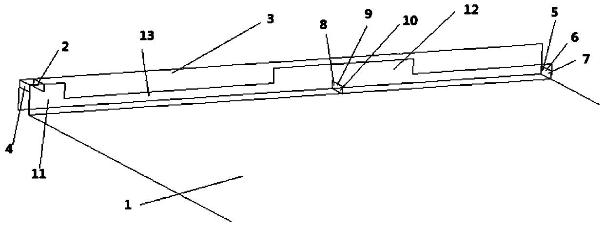
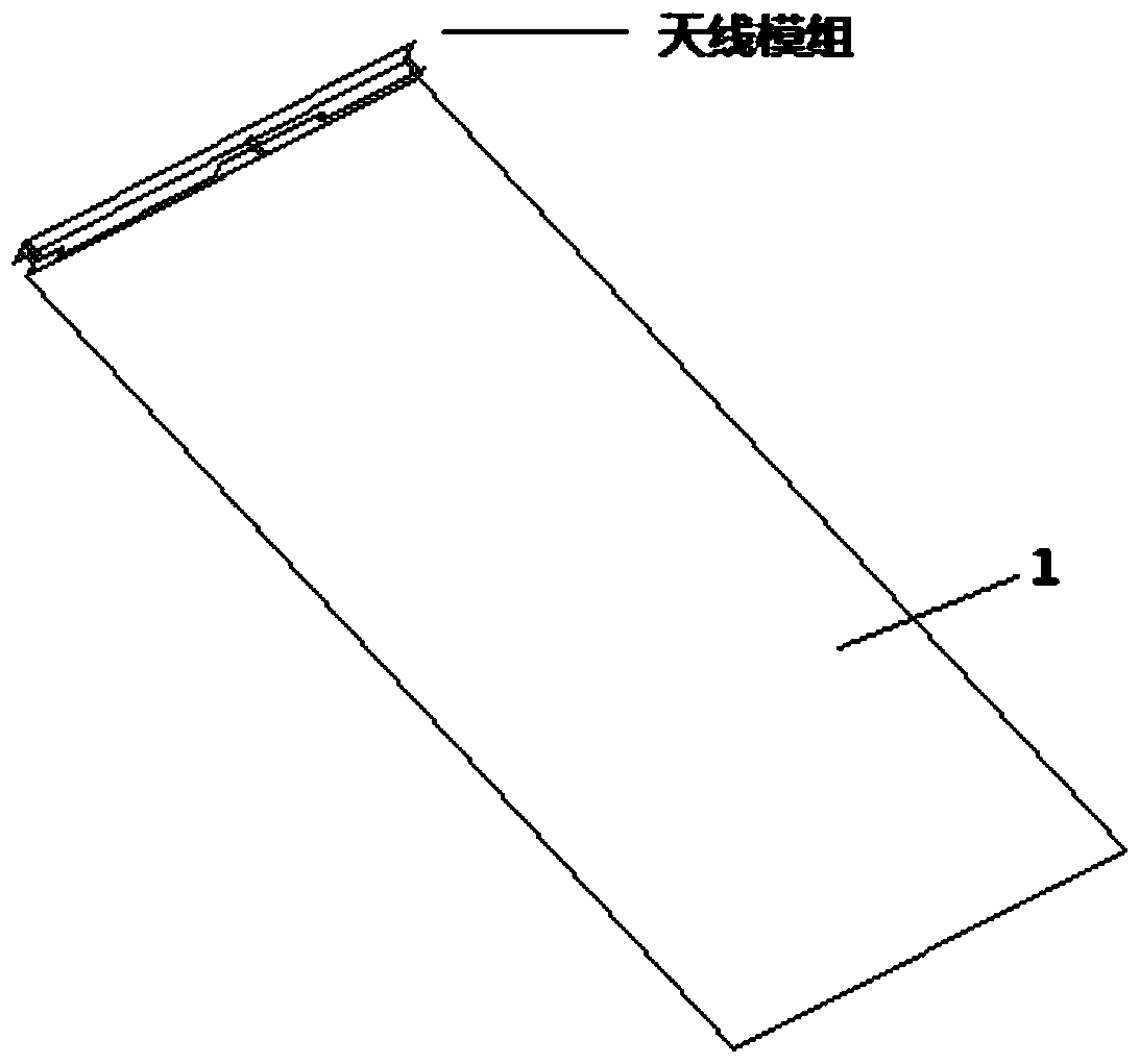
[0017] The main structure of the mobile phone antenna involved in this embodiment includes a grounding plate 1, a feeding point 2, a radiation patch 3, a feeding point matching 4, an end grounding point 5, an end grounding point RF switch 6, an end grounding point matching 7, a middle Indirect point 8, middle indirect point radio frequency switch 9, middle indirect point matching 10, microphone shielding wall 11, horn shielding wall 12 and battery shielding wall 13; an inductor with an inductance of 4.7nH is connected in parallel at the feeding point 2; radiation patch 3 Placed in a cavity with a rectangular strip (4mm*75mm) structure on the side wall of the mobile phone case, the space between the radiation patch 3 and the ground plate 1 of 3mm is the antenna clearance area; the terminal ground point 5 and the middle ground point 8 There are RF switches 6 and 9 with a single-pole four-throw structure connected respectively, each branch of the RF switches 6 and 9 is connected w...
PUM
 Abstract
Description
Claims
Application Information
 - R&D
- Intellectual Property
- Life Sciences
- Materials
- Tech Scout
- Unparalleled Data Quality
- Higher Quality Content
- 60% Fewer Hallucinations
Browse by: Latest US Patents, China's latest patents, Technical Efficacy Thesaurus, Application Domain, Technology Topic, Popular Technical Reports.
© 2025 PatSnap. All rights reserved.Legal|Privacy policy|Modern Slavery Act Transparency Statement|Sitemap|About US| Contact US: help@patsnap.com


