sliding door

A technology of sliding doors and door rows, which is applied in the field of sliding doors, can solve problems such as wasting door opening clearance, and achieve the effects of reducing floor space, saving door opening clearance, and eliminating stretching

Active Publication Date: 2022-05-10
HONGMEN ADVANCED TECH CORP
View PDF4 Cites 0 Cited by
  • Summary
  • Abstract
  • Description
  • Claims
  • Application Information

AI Technical Summary

Problems solved by technology

[0004] The technical problem to be solved by the present invention is to provide a translation door for the problem that the existing translation door wastes the clearance of the door opening.

Method used


Image

  • sliding door
  • sliding door
  • sliding door

Examples


no. 1 example

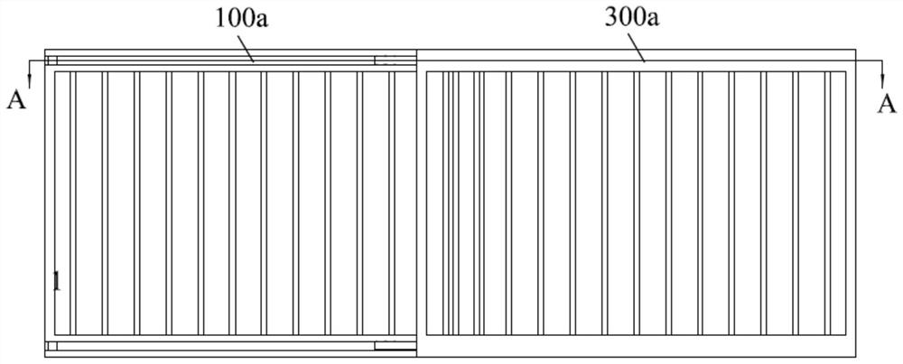
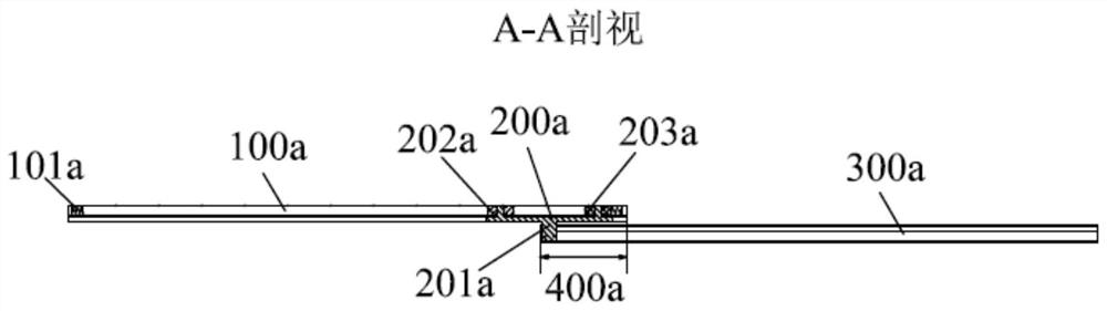
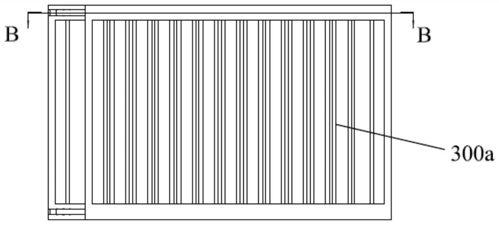
[0067] see Figure 5 to Figure 9 , the translational door of the first embodiment of the present invention includes a guide assembly 200, a door row assembly 100 and a door row assembly 300, and the door row assembly 100 includes a door row main body 105, a face beam 103, a face beam 104, and a door row top opening Limit 101, door closing limit 102 at the top of the door row, door opening limit 106 at the bottom of the door row, and door closing limit 107 at the bottom of the door row. The surface beam 103 is fixed on the top of the door row main body 105, and the surface beam 104 is fixed at the bottom of the main body 105 of the door row. The door row assembly 300 includes a door row main body 305, a face beam 303, a face beam 304, a door row top door opening limiter 301, a door row top door closing limiter 302, a door row bottom door opening limiter 306 and a door row bottom door closing limiter 307 , the face beam 303 is fixed on the top of the door row main body 305 , an...

no. 2 example

[0095] see Figure 10 , the translation door provided by the second embodiment of the present invention, the guide bracket 205 includes a first frame body 2051 and a second frame body 2052 arranged in parallel, and the first frame body 2051 and the second frame body 2052 are connected The middle frame body 2053.

[0096] The difference between this embodiment and the first embodiment is that the first guide includes a first guide wheel 201b rotatably connected to the first frame body 2051, and the second guide includes a first guide wheel 201b rotatably connected to A second guide wheel 202b on the second frame body 2052 . The guide bracket 205 is provided with a guide wheel shaft 2054 , and the first guide wheel 201b and the second guide wheel 202b are both rotatably connected to the corresponding guide wheel shafts 2054 . The outer end of the guide wheel shaft 2054 is provided with a hoop 206 to prevent the first guide wheel 201b and the second guide wheel 202b from fallin...

no. 3 example

[0099] see Figure 11 In the translation door provided by the third embodiment of the present invention, the guide bracket 501 includes a first frame body 5011 and a second frame body 5012 arranged in parallel, and the first frame body 5011 and the second frame body 5012 are connected The intermediate frame body 5013.

[0100] The difference between this embodiment and the second embodiment is that the first guide includes a first slider 502 fixedly connected to the first frame body 5011, and the second guide includes a first slider 502 fixedly connected to the first frame 5011. Describe the second slider 503 on the second frame body 5012. The guide bracket 501 is provided with an installation shaft 5014 , and the first slider 502 and the second slider 503 are installed on the respective corresponding installation shafts 5014 . The outer end of the installation shaft 5014 is provided with a hoop 504 to prevent the first sliding block 502 and the second sliding block 503 from...


PUM


Abstract

The invention relates to a translational door, comprising a plurality of door row assemblies, a guide assembly is arranged between two adjacent door row assemblies, and the guide assembly is slidingly connected with the two adjacent door row assemblies, so as to realize the The dislocation sliding of the two door row assemblies, the door row assembly is provided with a door opening limit and a door closing limit for limiting the guide assembly. When all the door row assemblies are fully pulled apart, the guide assembly abuts against the corresponding door closing limits of the two adjacent door row assemblies, and the length of all the door row assemblies when fully pulled is greater than or equal to the length of all the door row assemblies sum; when all the door row assemblies are fully folded, the guide assembly abuts against the corresponding door opening limits of the two adjacent door row assemblies, and the length of all the door row assemblies is equal to the length of the longest door row assembly length. Compared with the prior art, the occupied space of the door row assembly is reduced, and the utilization rate of the door opening is improved.

Description

technical field [0001] The invention belongs to the technical field of translation doors, in particular to a translation door. Background technique [0002] see Figure 1 to Figure 4 , the prior art discloses a translation door, including a first door row 100a, a first stop 101a, a second stop 102a, a guide wheel assembly 200a and a second door row 300a, the guide wheel assembly 200a includes a guide wheel bracket 201a, The first guide wheel 202a and the second guide wheel 203a. The first door row 100a and the second door row 300a are the main door body parts, the guide wheel assembly 200a is the main transmission part required for the contraction of the door row, the guide wheel bracket 201a, the first guide wheel 202a and the second guide wheel 203a are the guide wheels. The main components of the wheel assembly 200a, the first limiter 101a and the second limiter 102a serve as limiters when the first door row 100a and the second door row 300a are opened and closed. The f...

Claims


Application Information

Patent Timeline
Patent Type & Authority Patents(China)
IPC IPC(8): E06B11/04E05D15/06E05C17/62
CPCE06B11/026E06B11/045E05D15/0652E05D15/063E05C17/62
Inventor 何菲骆志敏
Owner HONGMEN ADVANCED TECH CORP
Why Eureka
Try Eureka