Constant device special for iron arm installation of high-voltage live-line operation vehicle

A technology of high-voltage electrification and work vehicles, applied in the direction of overhead lines/cable equipment, etc., can solve the problem that operators cannot take crossings, and achieve the effect of convenient and fast installation

Inactive Publication Date: 2016-06-29
王磊
View PDF0 Cites 0 Cited by
  • Summary
  • Abstract
  • Description
  • Claims
  • Application Information

AI Technical Summary

Problems solved by technology

2. Operators cannot

Method used


Image

  • Constant device special for iron arm installation of high-voltage live-line operation vehicle

Examples


Embodiment Construction

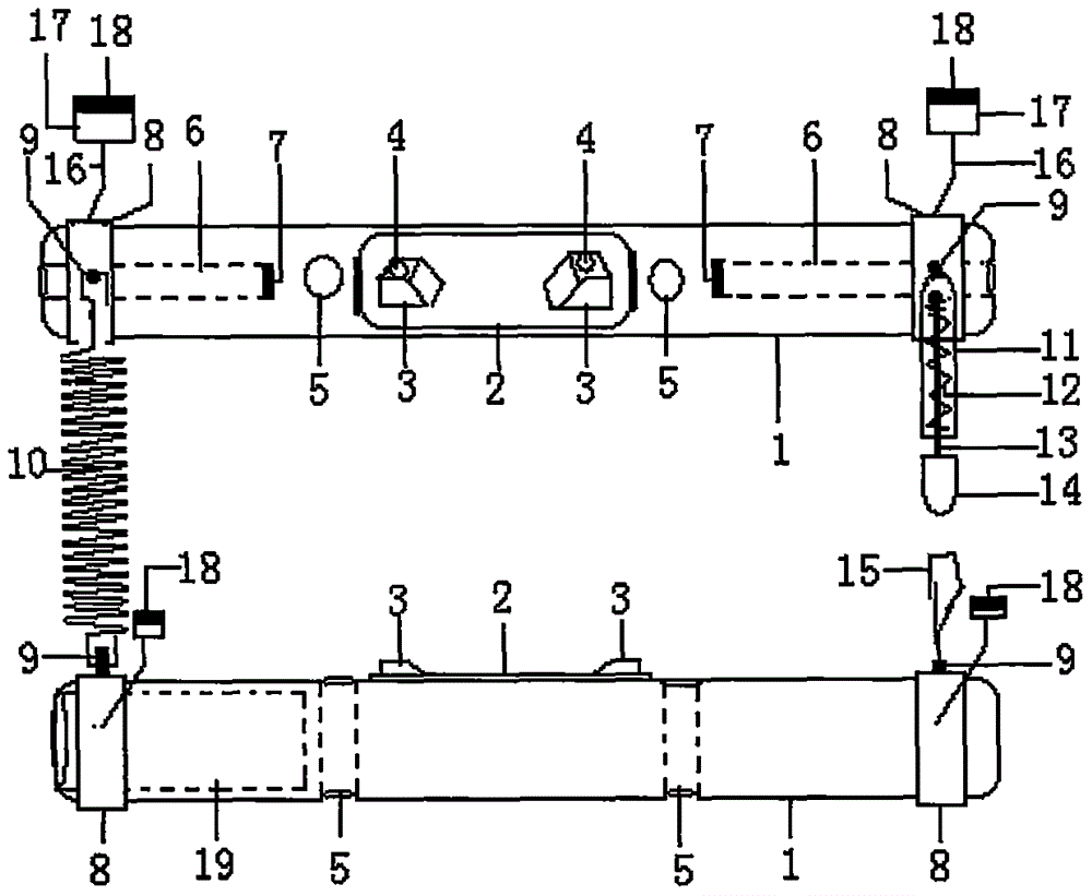
[0009] The accompanying drawings show the structure of the present invention, the high-strength insulating rod 1, the middle position of the high-strength insulating rod 1 is provided with a reinforced metal plate 2, and the two sides of the reinforced metal plate 2 are provided with trapezoidal ears 3, and the upper part of the trapezoidal ear 3 is fixed. Holes 4, bolt-through holes 5 are set on the outer sides of the reinforced metal plate 2, pull-bolt placement holes 6 are set in the middle of both ends of the high-strength insulating rod 1, and a first circular magnet 7 is arranged at the bottom of the pull-bolt placement holes 6. The two ends of the strength insulating rod 1 are provided with end jackets 8, and the middle position of one end jacket 8 is provided with an extension spring seat 9, and a hard extension spring 10 is arranged between the extension spring seats 9, and a spring support pipe 11 is arranged on the other end jacket 8, A support spring 12 is arranged ...


PUM


Abstract

The invention discloses a special stabilizer used for installing iron poles on a high-voltage live working vehicle. Because a second round magnet is placed in the room where the round magnet at the upper end of the outer support column outside the outer casing of the two ends of the high-strength insulating rod is used, Its characteristics are: after the two high-strength insulating rods are fixed to the electric pole, the second round magnet can be realized. The two iron poles can be placed parallel to the square of the second round magnet. When the two iron poles After being placed on the top of the second round magnet, the second round magnet can also realize that it can be firmly adsorbed and firmly attached to the plane at the bottom of the two iron poles.

Description

technical field [0001] The invention relates to live work, and directly relates to a special stabilizer used for installing iron poles on a high-voltage live work vehicle, and is especially suitable for close-distance work on an insulated arm bucket car and a main power line in a charged state. Background technique [0002] In the construction of overhead lines, a single iron pole and supporting insulators are usually used to support the main power line in the straight section. An insulator is used to tension the mains power line. When installing a single iron pole construction, it is usually done by one person. The construction of the two iron poles must be completed by the cooperation of two people. The method is: start from the top of the pole to measure the position of each cross-arm on the pole and mark it. Put the cross arm and the M-shaped iron together, and align the fixed bolt holes of the two, then make the M-shaped iron downward, put the two together on the ins...

Claims


Application Information

Patent Timeline
IPC IPC(8): H02G1/04
CPCH02G1/04
Inventor 王磊纪昂尹衍武吕清杰高原
Owner 王磊
Why Eureka
Try Eureka