Design method of connecting column for reducing temperature rise at overlap position between electric bus bars

A busbar overlapping and design method technology, applied in the direction of cooling busbar devices, etc., can solve the problems of increased space occupied by busbars, increased equipment manufacturing costs, and increased busbar consumption, so as to reduce wiring width and save resources , the effect of reducing the current density

Inactive Publication Date: 2016-06-29
龚柱
View PDF5 Cites 9 Cited by
  • Summary
  • Abstract
  • Description
  • Claims
  • Application Information

AI Technical Summary

Problems solved by technology

Increasing the overlapping length will increase the amount of busbars, which will increase the manufacturing cost of the equipment
The bolts used for fastening will reduce the electrical clearance or phase-to-phase distance between the busbars. In order to keep the electrical clearance or phase-to-phase distance unchanged, the distance between the busbars needs to be increased, and increasing the distance between the busbars will inevitably lead to the occupation of the busbars. bigger space

Method used


Image

  • Design method of connecting column for reducing temperature rise at overlap position between electric bus bars
  • Design method of connecting column for reducing temperature rise at overlap position between electric bus bars
  • Design method of connecting column for reducing temperature rise at overlap position between electric bus bars

Examples


Embodiment 2

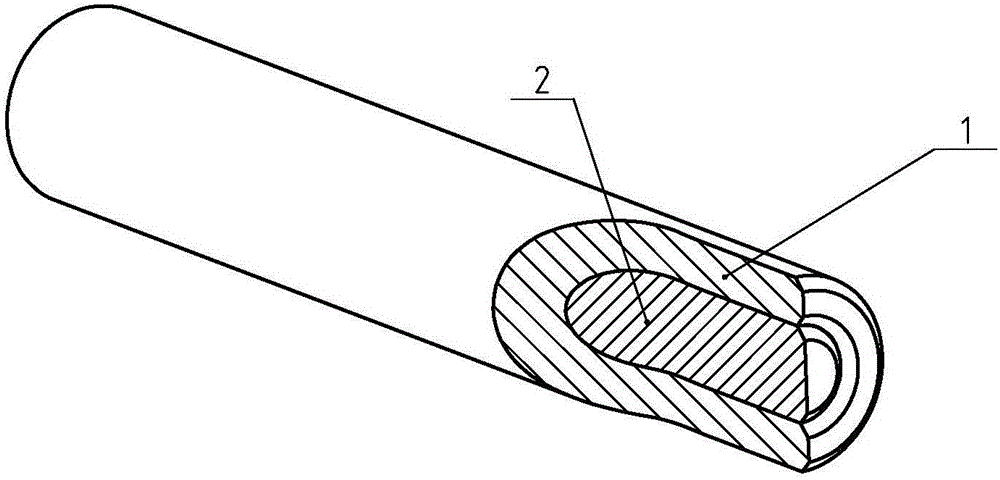
[0068] The material of the first columnar part 1 in the first embodiment is changed to a copper alloy, and the material of the first columnar part 2 is changed to an aluminum alloy. Since the hardness of the alloy is relatively high, the first columnar part 2 can be placed in a low temperature environment ( 5 degrees) for a period of time (5 minutes), while the first columnar part 1 is stored for a period of time (5 minutes) in a high temperature environment (80 degrees), with the help of the effect of thermal expansion and contraction, the inner diameter of the first columnar part 1 Slightly larger, while the outer diameter of the first columnar part 1 is slightly smaller, and then the first columnar part 2 can be easily assembled into the first columnar part 1. After the assembled connecting column returns to normal temperature, the first columnar part 1 Interference fit with the first columnar part 2 can be realized. The diameter and length of the coupling column disclosed ...

Embodiment 3

[0070] Such as Figure 14-15 As shown, the inside of the second columnar part 2 is coaxially provided with a second through hole 7, the first columnar part 6 has a hollow structure, the second columnar part 2 penetrates the first columnar part 1, and the outer cylindrical surface of the first columnar part 1 A first through hole 6 is arranged radially, the first through hole 6 communicates with the second through hole 7 , and the first through hole 6 is located in the axial middle of the first columnar portion 1 .

[0071] Due to the setting of the through holes 6 and 7, when the connecting column is inserted into the prefabricated hole of the first busbar, the air in the prefabricated hole can be smoothly discharged from the second through hole 7, so that the connecting column can be smoothly assembled in place , when the second busbar is inserted into the already installed coupling column, the air in the prefabricated hole of the second busbar can be smoothly discharged from...


PUM


Abstract

The invention discloses a design method of a connecting column for reducing temperature rise at an overlap position between electric bus bars, belongs to the field of power equipment, and particularly relates to a design method of a connecting column. The design method of the connecting column disclosed by the invention comprises the following steps: providing first columnar parts which are in interference fit with prefabricated holes in the electric bus bars, wherein the first columnar parts are electrically conductive; coaxially arranging second columnar parts which are electrically conductive in the first columnar parts; making the first columnar parts be in interference fit with the second columnar parts; and making thermal expansion coefficients of the second columnar parts be greater than the thermal expansion coefficients of the first columnar parts. The connecting column made by the design method disclosed by the invention has the beneficial effects that 1, more electric conduction area is formed at a same overlap length, so that the current density is lowered, and low temperature rise of the bus bars is realized; 2, a using quantity of the bus bars is reduced, and resources are saved; 3, electric clearances or space distances are increased, and the electrical safety of equipment is enhanced; and 4, arrangement widths of the bus bars are reduced, so that space occupied by the bus bars can be reduced.

Description

technical field [0001] The invention relates to the field of power equipment, in particular to a design method for a connecting column of a power busbar. Background technique [0002] In the field of power distribution, the connection of two power busbars is usually overlapped and then fastened with bolts. Such as figure 1 In the upper half of the busbar, this connection method needs to overlap the two busbars by a certain length, so that the current density of the contact surface can be maintained within a certain range, so that the temperature rise at the connection can meet the relevant standards. In order to reduce the temperature rise of power equipment, it is usually necessary to increase the overlapping length of the busbars to increase the contact area, thereby reducing the current density of the contact surface, and finally making the equipment have a lower temperature rise. Increasing the overlapping length will increase the amount of busbars used, thereby increa...

Claims


Application Information

Patent Timeline
Patent Type & Authority Applications(China)
IPC IPC(8): H02G5/10
CPCH02G5/10
Inventor 不公告发明人
Owner 龚柱
Why Eureka
Try Eureka