Eureka AIR delivers breakthrough ideas for toughest innovation challenges, trusted by R&D personnel around the world.

PIN installing machine

A technology of nailing machine and base, which is applied in the field of PIN nailing machine, which can solve the problems of affecting production efficiency, abnormal position of PIN nailing hole deviation, abnormal production quality of circuit boards, etc.

Active Publication Date: 2016-06-29
NEW FOUNDER HLDG DEV LLC +1
View PDF4 Cites 2 Cited by
  • Summary
  • Abstract
  • Description
  • Claims
  • Application Information

AI Technical Summary

Problems solved by technology

[0004] In the related technology, there are many defects in the PIN nailing machine: the positioning function of the PIN nail positioning device is mainly two parts of the guide post and the slider, which is characterized by "single weight and single point" fixing, that is, the slider is fixed with a single screw At a certain point of the guide post, when the PIN nail on the circuit board is positioned, the circuit board and the square bar collide with each other, which can easily cause the positioning bar to loosen, resulting in the phenomenon that the position of the upper PIN nail is abnormal, causing the circuit board to be damaged. Abnormal production quality, which affects production efficiency

Method used

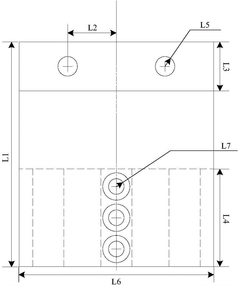
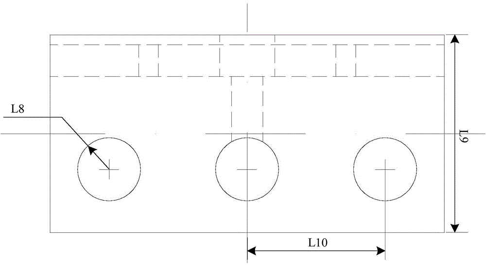

Image

  • PIN installing machine
  • PIN installing machine
  • PIN installing machine

Examples


Embodiment Construction

[0028] In order to be able to understand the above objectives, features and advantages of the present invention more clearly, the present invention will be further described in detail below in conjunction with the accompanying drawings and specific embodiments. It should be noted that the embodiments of the application and the features in the embodiments can be combined with each other if there is no conflict.

[0029] In the following description, many specific details are set forth in order to fully understand the present invention. However, the present invention can also be implemented in other ways different from those described here. Therefore, the protection scope of the present invention is not limited to the specific details disclosed below. Limitations of the embodiment.

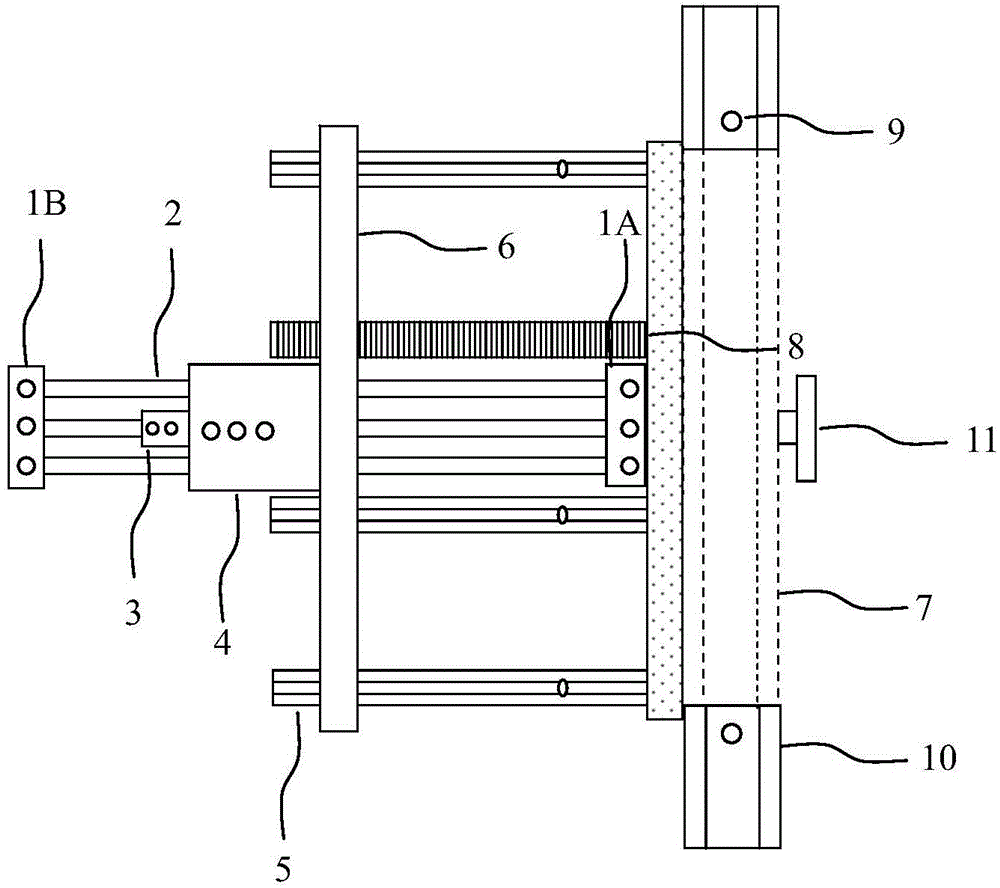
[0030] figure 1 The schematic diagram of the PIN nailing machine according to the embodiment of the present invention is shown.

[0031] Such as figure 1 As shown, the PIN nailing machine according to the...


PUM


Abstract

The invention provides a PIN installing machine, and the machine comprises a substrate which comprises a front substrate and a rear substrate; a guide pillar which is laterally disposed between the front and rear substrates; a stopping structure which is disposed on the guide pillar; and a sliding block which is disposed on the guide pillar, wherein a side wall of the sliding block is provided with at least two first limiting holes. When the sliding block abuts against the stopping structure which completes the clamping fixing, a first assembly column passes through the first limiting holes and enables the sliding block to be compressed on the guide pillar. The machine also comprises a positioning ring, and a cylindrical wall of the positioning ring is provided with at least two second limiting holes. The positioning ring is disposed on the guide pillar in a sleeving manner. When the positioning ring abuts against the sliding block compressing the guide pillar, a second assembly column passes through the second limiting holes and enables the positioning ring to be compressed on the guide pillar. According to the technical scheme of the invention, the machine improves the fixing of a to-be-pinned board material, and improves the alignment precision of the board material and a pin.

Description

Technical field [0001] The invention relates to the technical field of circuit boards, in particular to a PIN nailing machine. Background technique [0002] The drilling process is the most important process in the printed circuit board process. The quality of the drilling has a considerable influence on the post-processing process of the circuit board. Therefore, the control of the drilling quality is very important. With the rapid development of electronic communication technology and the development trend of "light, thin and small" electronic products, drilling technology is changing with each passing day. The drilling methods are mainly divided into: mechanical drilling, laser burning, photosensitive drilling, etc. . Different equipment technologies and drilling processes are applied to the production of different levels of circuit boards. The content involved in this application is mainly the PIN nailing process of "PIN-up→drilling→inspection" in the mechanical drilling pro...

Claims


Application Information

Patent Timeline
IPC IPC(8): H05K3/00
Inventor 董彦明车世民谢继敏
Owner NEW FOUNDER HLDG DEV LLC
Why Eureka
Eureka Blog
Learn More