Device for punching parts

A technology of stamping processing and parts, applied in the direction of feeding device, stripping device, storage device, etc., can solve the problems of low degree of automation and unsatisfactory use effect

Inactive Publication Date: 2016-07-06
WUHU HONGFEI MACHINERY CO LTD
View PDF0 Cites 19 Cited by
  • Summary
  • Abstract
  • Description
  • Claims
  • Application Information

AI Technical Summary

Problems solved by technology

[0005] The existing stamping device cannot perform stamping operations continuously, the...

Method used


Image

  • Device for punching parts

Examples


Embodiment Construction

[0025] It should be noted that, in the case of no conflict, the embodiments in the present application and the features in the embodiments can be combined with each other; the present invention will be described in detail below with reference to the accompanying drawings and in combination with the embodiments.

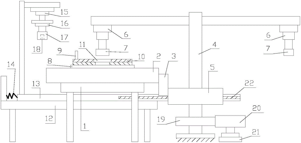
[0026] refer to figure 1 :

[0027] A device for stamping parts proposed by the present invention includes a conveying part, a plurality of molds, a stamping part and a material taking part.

[0028] The transmission part includes a supporting platform 1, a moving plate 2, and a rack 3. There is a moving channel on the supporting platform 1, and the moving channel is arranged horizontally; the moving plate 2 is movably installed on the moving channel, and the moving plate 2 is arranged horizontally; the rack 3 is installed on the side of the moving plate 2, and the length direction of the rack 3 is parallel to the length direction of the moving channel.

[0029] A p...


PUM


Abstract

The invention discloses a device for stamping parts, which includes a transmission part, a plurality of molds, and a stamping part; the transmission part includes a support platform, a moving plate, and a rack; The channel is set horizontally; the moving plate is movably installed on the moving channel, and the moving plate is set horizontally; the rack is installed on the side of the moving plate, and the length direction of the rack is parallel to the length direction of the moving channel; multiple molds are arranged along the length of the moving channel The direction intervals are installed on the moving board, and the distance between any two adjacent moving boards is equal. The invention has good processing effect and high processing precision.

Description

technical field [0001] The invention relates to the technical field of stamping equipment, in particular to a device for stamping parts. Background technique [0002] Stamping relies on presses and molds to apply external forces to plates, strips, pipes, and profiles to cause plastic deformation or separation to obtain workpieces (stampings) of required shape and size. [0003] Stamping processing is a production technology that uses the power of conventional or special stamping equipment to directly subject the sheet to deformation force and deform in the mold, so as to obtain product parts of a certain shape, size and performance. Sheet metal, mold and equipment are the three elements of stamping processing. [0004] According to the stamping processing temperature, it is divided into hot stamping and cold stamping. The former is suitable for sheet metal processing with high deformation resistance and poor plasticity; the latter is carried out at room temperature and is ...

Claims


Application Information

Patent Timeline
IPC IPC(8): B21D22/08B21D45/00B21D43/00B21D43/14
CPCB21D22/08B21D43/003B21D43/14B21D45/003
Inventor 陶琦
Owner WUHU HONGFEI MACHINERY CO LTD
Why Eureka
Try Eureka