Pipe bending machine

A technology for pipe bending and pipe fittings, which is applied to other manufacturing equipment/tools, manufacturing tools, etc., can solve the problems of increasing dependence on skilled workers, inability to ensure uniform quality, and low efficiency, so as to reduce personnel costs and achieve high mechanical coordination efficiency. The effect of improving productivity

Active Publication Date: 2016-07-06
北京正兴天宝自动化科技有限公司
View PDF10 Cites 2 Cited by
  • Summary
  • Abstract
  • Description
  • Claims
  • Application Information

AI Technical Summary

Problems solved by technology

[0003] The traditional pipe bending process requires manual operation, which is inefficient and cannot guarantee uniform quality. Skilled workers are required to manually fix and use the pressing plate, which increases the dependence on skilled workers and is not conducive to development

Method used


Image

  • Pipe bending machine
  • Pipe bending machine
  • Pipe bending machine

Examples


Embodiment Construction

[0028] The application will be further described in detail below in conjunction with the accompanying drawings and embodiments. It should be understood that the specific embodiments described here are only used to explain related inventions, rather than to limit the invention. It should also be noted that, for ease of description, only parts related to the invention are shown in the drawings.

[0029] It should be noted that, in the case of no conflict, the embodiments in the present application and the features in the embodiments can be combined with each other. The present application will be described in detail below with reference to the accompanying drawings and embodiments.

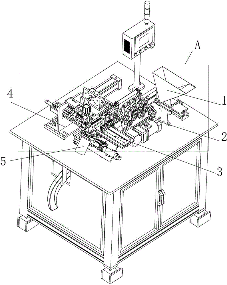
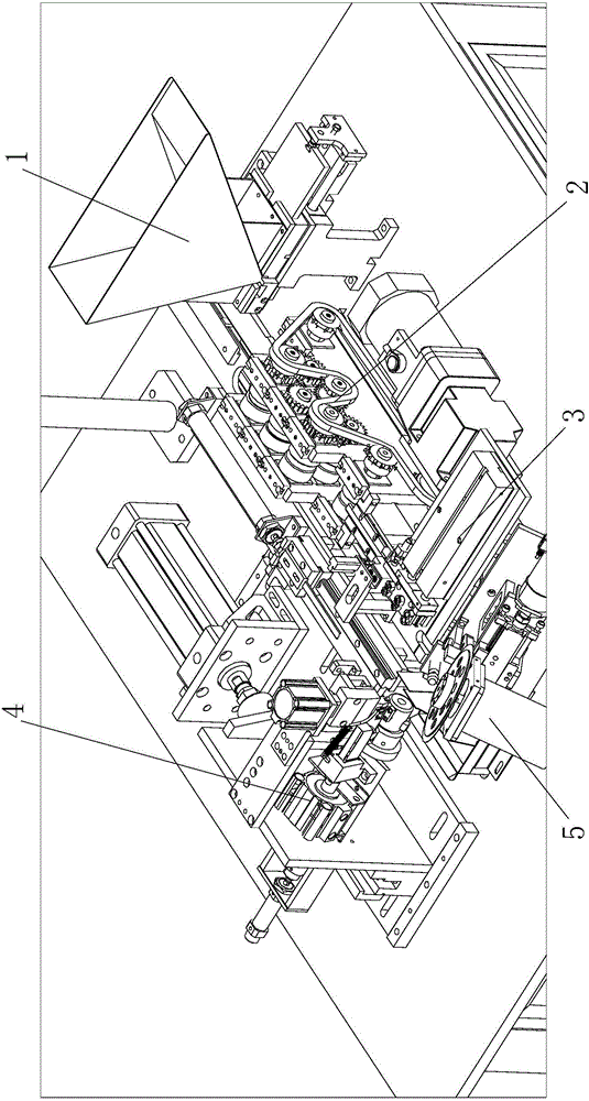
[0030] The invention discloses a pipe fitting bending mechanism, see figure 1 and figure 2 , the bending mechanism includes a flattening mechanism 2, which is used to flatten the pipe, and the flattened pipe is called a flat pipe below, and also includes a flat pipe bending mechanism 4, which is...


PUM


Abstract

The invention discloses a pipe bending machine. The pipe bending machine comprises a flattening mechanism, a flat pipe bending mechanism and a cutting mechanism. The flattening mechanism is provided with an input part for entering of a pipe, a pressing part flattening the pipe, and an output part outputting the flattened pipe. The flat pipe bending mechanism is provided with a flat pipe conveying part and a rotating pipe bending part. The flat pipe conveying part receives the flat pipe and conveys the flat pipe to the rotating pipe bending part, and the rotating pipe bending part bends the flat pipe into a bent pipe. The cutting mechanism is located on one side of the flat pipe bending mechanism and used for cutting the bent pipe. Compared with the prior art, the pipe bending machine has the following beneficial effects that the multiple mechanisms cooperate with one another, the pipe is flattened, then bent and cut, work can be automatically finished, the machine cooperation efficiency is high, and the production efficiency is improved; and the requirement for operators is low, and the operator cost is reduced.

Description

technical field [0001] The present disclosure generally relates to the field of mechanical processing, specifically to the field of pipe fitting processing, and in particular to a pipe fitting bending machine. Background technique [0002] At present, when bending pipe fittings, each step is manually completed, such as manual feeding, and pipe fittings are flattened, and the flattened pipe fittings (flat pipes) are manually fixed on the bending machine, and then used The pressure plate is pressed against the flattened tube. Turn on the machine manually to bend the flat tube. [0003] The traditional pipe bending process requires manual operation, which is inefficient and cannot guarantee uniform quality. Skilled workers are required to manually fix and use the pressing plate, which increases the dependence on skilled workers and is not conducive to development. Contents of the invention [0004] In view of the above-mentioned defects or deficiencies in the prior art, it ...

Claims


Application Information

Patent Timeline
IPC IPC(8): B23P23/04B21D31/00B21D7/00
CPCB21D7/00B21D31/00B23P23/04
Inventor 孙征
Owner 北京正兴天宝自动化科技有限公司
Why Eureka
Try Eureka