Eureka AIR delivers breakthrough ideas for toughest innovation challenges, trusted by R&D personnel around the world.

Plastic packaging mold

A plastic sealing mold and mold flow technology, applied in the direction of coating, etc., can solve problems such as excessive air, circuit board air bubbles, and affecting the quality of plastic sealing products, so as to increase the extrusion time, reduce the probability of air bubbles, and prolong the proximity to the exhaust groove. the effect of time

Active Publication Date: 2016-07-06
HUANWEI ELECTRONICS SHANGHAI CO LTD
View PDF4 Cites 7 Cited by
  • Summary
  • Abstract
  • Description
  • Claims
  • Application Information

AI Technical Summary

Problems solved by technology

[0004] In the existing mold closing process, when the mold flow is close to the exhaust groove, the mold clamping pressure directly reaches the set final mold clamping pressure. If too much air is incorporated into the mold cavity when the molding compound is injected, more air may remain in the mold cavity , eventually causing air bubbles in the packaged circuit board, affecting the quality of plastic packaged products

Method used


Image

  • Plastic packaging mold
  • Plastic packaging mold
  • Plastic packaging mold

Examples


Embodiment Construction

[0026] In order to more clearly illustrate the embodiments of the present invention or the technical solutions in the prior art, the specific implementation manners of the present invention will be described below with reference to the accompanying drawings. Obviously, the accompanying drawings in the following description are only some embodiments of the present invention, and those skilled in the art can obtain other accompanying drawings based on these drawings and obtain other implementations.

[0027] In order to make the drawing concise, each drawing only schematically shows the parts related to the present invention, and they do not represent the actual structure of the product. In addition, to make the drawings concise and easy to understand, in some drawings, only one of the components having the same structure or function is schematically shown, or only one of them is marked. Herein, "a" not only means "only one", but also means "more than one".

[0028] In one emb...


PUM


Abstract

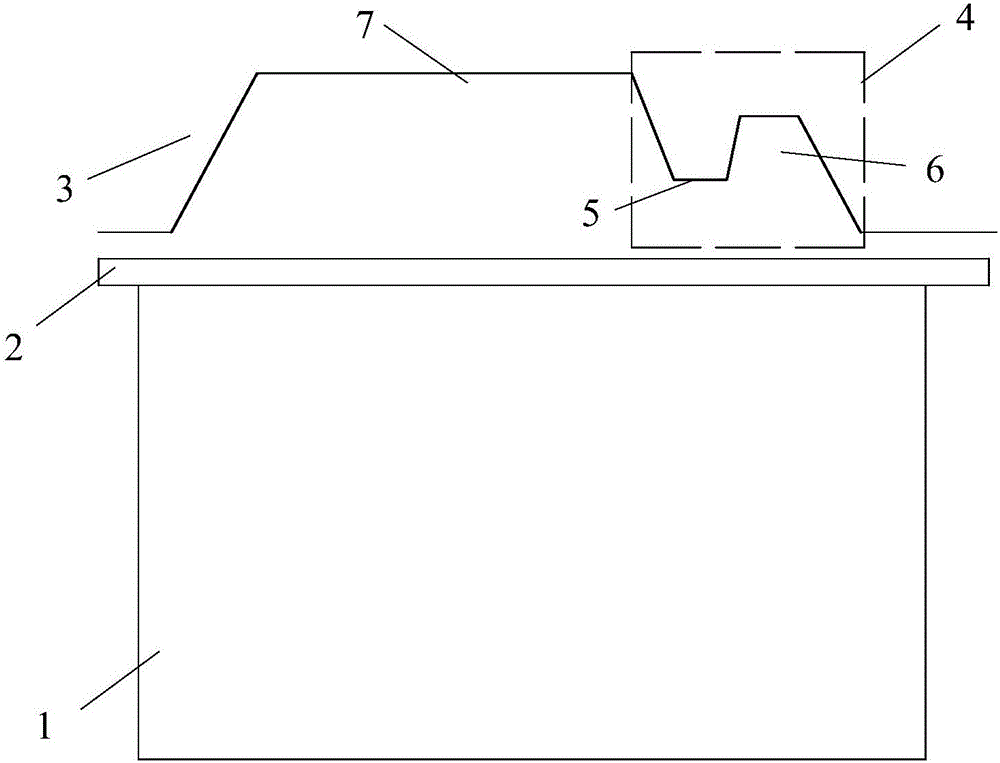
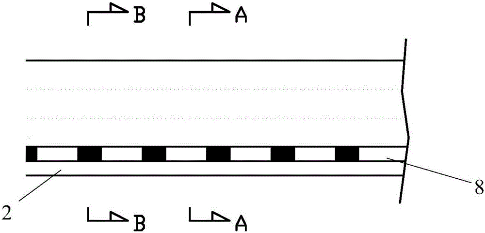
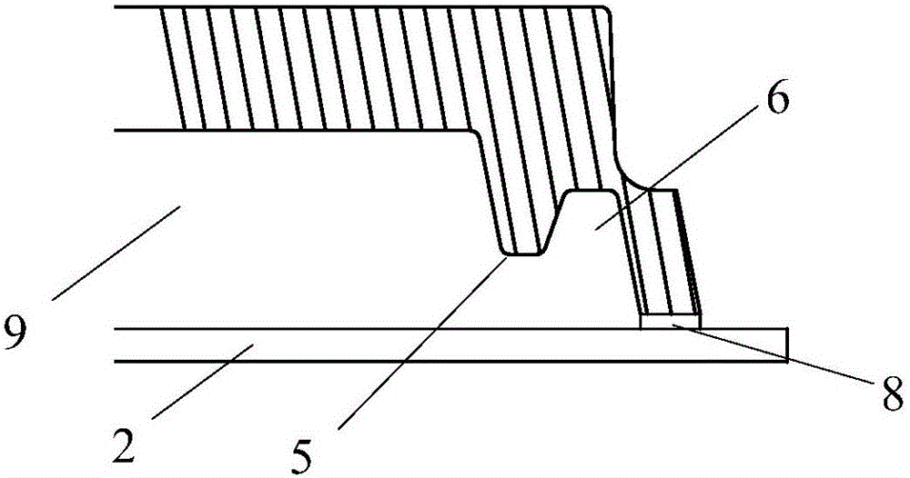
The invention discloses a plastic packaging mold and relates to the field of plastic packaging of semiconductors. The plastic packaging mold comprises an upper mold body and a lower mold body used for containing a PCB. The lower surface of the upper mold body is sunken towards the upper surface of the upper mold body to form a groove. When the upper mold body and the lower mold body are pressed and combined, a molding cavity is formed between the groove and the PCB. One end of the molding cavity communicates with an air discharge duct. The end, close to the air discharge duct, of the groove is provided with a buffer area used for balancing molding flow. The molding flow in the molding cavity is balanced through the buffer area. The discharge time of the air in the molding cavity is prolonged, and the product quality is improved.

Description

technical field [0001] The invention relates to the field of semiconductor plastic packaging, in particular to a plastic packaging mold. Background technique [0002] Resin Transfer Molding (RTM, Resin Transfer Molding) has a history of nearly 60 years and is widely used in the semiconductor industry. RTM refers to a process technology in which a low-viscosity resin flows in a closed mold, infiltrates a reinforcing material, and solidifies and forms, and belongs to the category of liquid forming or structural liquid forming technology of composite materials. [0003] In the general RTM mold, there will be an air venting (Air Venting) connecting the cavity (Cavity) area, which is convenient for extracting and extruding the air in the cavity (Cavity) when closing the mold, so as to prevent the problem of non-filling in the product . The cavity is formed by pressing the upper mold of the mold on a printed circuit board (PCB, Printed Circuit Board). [0004] In the existing m...

Claims


Application Information

Patent Timeline
Patent Type & Authority Applications(China)
IPC IPC(8): B29C45/14B29C45/34B29C33/18
CPCB29C45/14065B29C45/34B29C2045/14155
Inventor 周青云郭静
Owner HUANWEI ELECTRONICS SHANGHAI CO LTD
Why Eureka
Eureka Blog
Learn More