
Heat pump evaporation heat recovery combination device and waste liquid high-efficiency concentration method

A combined device and heat pump evaporation technology, applied in heat recovery systems, chemical instruments and methods, energy-saving heating/cooling, etc., can solve problems such as difficult to improve, waste of heat energy, increased operating costs, etc.

Active Publication Date: 2019-02-05
DONGGUAN DONGYUAN ENVIRONMENTAL TECH CO LTD
View PDF3 Cites 0 Cited by
  • Summary
  • Abstract
  • Description
  • Claims
  • Application Information

AI Technical Summary

Problems solved by technology

[0002] At present, the method of evaporating the waste liquid is generally adopted, that is, the waste liquid is continuously evaporated and the water is gradually concentrated; however, the evaporation efficiency in the prior art is limited and it is difficult to improve, which affects the waste liquid treatment efficiency. Evaporation efficiency requires an increase in heat energy input, which leads to an increase in operating costs and does not conform to the current concept of energy conservation
[0003] In fact, in the existing evaporative concentration system, a lot of heat energy will be wasted. In the patent application of the present invention, a new technical solution has been studied, which uses the heat energy in the original evaporative concentration system to evaporate the waste liquid Preheating treatment before, to greatly improve the efficiency of evaporation and concentration without increasing energy consumption

Method used


Image

  • Heat pump evaporation heat recovery combination device and waste liquid high-efficiency concentration method

Examples


Embodiment Construction

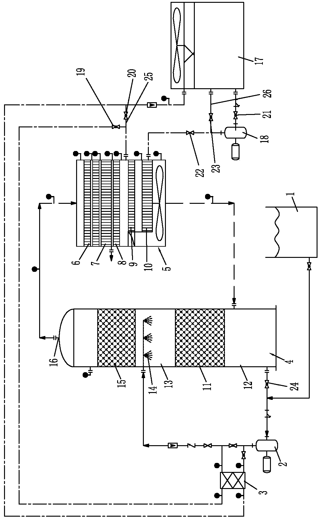
[0036] Please refer to figure 1 As shown, it shows the specific structure of the embodiment of the present invention. This new heat pump 5 evaporation heat recovery combination device includes a waste liquid storage tank 1, a circulation pump 2, a heat exchanger 3, an evaporation tank 4 and a heat pump 5 , wherein, the heat pump 5 has a heat recovery device 6, an evaporator and a condenser. Here, the evaporator includes a primary evaporator 7 and a secondary evaporator 8 connected in sequence, and the condenser includes a sequential The first-stage condenser 9 and the second-stage condenser 10 are connected; of course, multi-stage or single-stage designs can also be designed as required.

[0037] The aforementioned heat exchanger 3 has a first medium channel and a second medium channel, and the aforementioned waste liquid storage barrel 1 is connected to the inlet of the aforementioned first medium channel through a circulation pump 2; the aforementioned evaporator 4 is equipp...


PUM


Abstract

The invention discloses a novel heat pump evaporation heat recovery combined device and an efficient effluent concentration method.A suction pump is utilized for sucking effluent into an evaporation tank and spraying the effluent towards filler, hot and dry air exhausted by a heat pump and the sprayed effluent carry out heat exchange, water in the effluent is evaporated, and a concentrated solution obtained in the evaporation tank is circulated through the suction pump and enters the evaporation tank to be evaporated continuously; hot air obtained after heat exchange is sent back to the heat pump from the top of the evaporation tank, subjected to heat recovery through a heat recovery device in the heat pump and then passes through an evaporator to obtain condensate water and first cooling gas; before the effluent enters the evaporation tank, a heat exchanger is arranged to utilize the first cooling gas for preheating the effluent, the preheated effluent enters the evaporation tank and is sprayed towards the filler again, second cooling gas obtained after the first cooling gas releases heat is sent back to a condenser of the heat pump, and the hot and dry air is obtained under the action of the condenser.In this way, on the premise of not increasing energy consumption, evaporation and concentration efficiency is greatly improved.

Description

technical field [0001] The invention relates to the technology in the field of waste liquid evaporation and concentration, in particular to a novel heat pump evaporation heat recovery combination device and a waste liquid high-efficiency concentration method. Background technique [0002] At present, the method of evaporating the waste liquid is generally adopted, that is, the waste liquid is continuously evaporated and the water is gradually concentrated; however, the evaporation efficiency in the prior art is limited and it is difficult to improve, which affects the waste liquid treatment efficiency. Evaporation efficiency requires an increase in thermal energy input, which leads to an increase in operating costs and does not conform to the current concept of energy conservation. [0003] In fact, in the existing evaporative concentration system, a lot of heat energy will be wasted. In the patent application of the present invention, a new technical solution has been studi...

Claims


Application Information

Patent Timeline
Patent Type & Authority Patents(China)
IPC IPC(8): C02F1/12
CPCY02B30/52
Inventor 肖应东王延辉肖勇辉兰文青
Owner DONGGUAN DONGYUAN ENVIRONMENTAL TECH CO LTD
Learn More