Automatic thread winding and cutting integrated winder

A technology of automatic thread winding and bobbin winder, which is applied to bobbin winding in sewing machines, sewing equipment, textiles and paper making, etc. It can solve the problems of high cost, troublesome and time-consuming operation, complicated installation, etc., and achieves convenient operation and high thread volume. Adjust the effect of humanization

Inactive Publication Date: 2016-07-06
JACK SEWING MASCH CO LTD
View PDF7 Cites 17 Cited by
  • Summary
  • Abstract
  • Description
  • Claims
  • Application Information

AI Technical Summary

Benefits of technology

This new design allows for better control over how much space on an optical fiber cable can hold up wire without being filled too many times by manually adding or removing loops from it. Additionally, there are fewer steps needed when changing threads during production compared to previous designs. Overall, these improvements make the process easier and less expensive than current methods.

Problems solved by technology

This patented technical problem addressed in this patents relates to improving the efficiency or ease at which threads are unwrapped during the process of creation of stitches used in sewn machines. Current methods involve manual operation involving multiple steps before it becomes possible to secure the final thread ends properly, making installation difficult and expensive.

Method used


Image

  • Automatic thread winding and cutting integrated winder
  • Automatic thread winding and cutting integrated winder
  • Automatic thread winding and cutting integrated winder

Examples


Embodiment 1

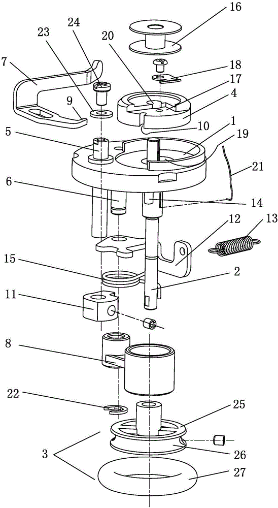
[0022] Embodiment one: see figure 1 —3:

[0023] An automatic winding and secant integrated wire winder, comprising a main body of the wire winder 1, on which a main shaft 2 of the wire winder capable of translating relative to the main body of the wire winder 1 is arranged, and the winding The lower end of the winder main shaft 2 is fixedly provided with a winding wheel 3, and the winding liner 4 is connected to the upper end of the winding liner main shaft 2 and is located above the main seat 1 of the winding liner, and the winding liner 4 above the winding liner main shaft 2 For set bobbin 16. Winder main seat 1 is also provided with winding camshaft 5, pin 6, and winding camshaft 5 is provided with crimping control board 7, and one end of winding device connecting rod 8 is sleeved on the winding device main shaft 2, and the other end is set on the pin 6, and the 7-position pressing control board is arranged above the main seat 1 of the winding device, and the winding cam...

Embodiment 2

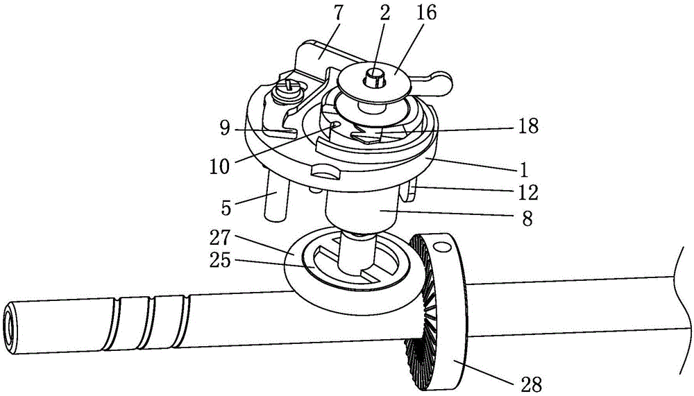
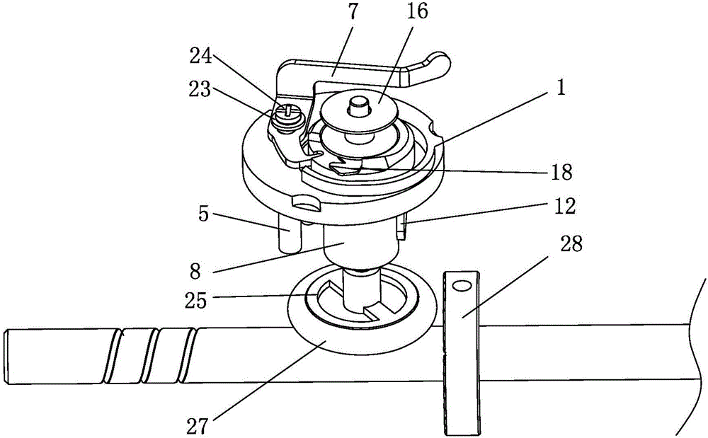
[0036] Embodiment two: see Figure 4 , 5 :

[0037] The structure of this embodiment is basically the same as that of Embodiment 1, the difference lies in the structure of the braking device:

[0038] Described braking device comprises the brake cam 29 that is arranged on the lower end of the main shaft 2 of the winder or is arranged on the winding wheel with a set track, the limit card slot 30 is arranged on the brake cam 29, and the winding camshaft 5 can Connect with the limit card slot 30 to realize braking.

[0039] The working principle of this embodiment:

[0040] A braking cam 29 with a specific track is added on the lower end of the winding device main shaft 2 or on the winding wheel, and braking is performed by the relative position change of the braking cam 29 and the winding camshaft 5 . Such as Figure 4 Shown is a schematic view of the wire winder when it is working, the wire pressing control plate 7 is pulled, the O-ring 27 is in contact with the wire windi...


PUM


Abstract

The invention belongs to the technical field of sewer parts, and particularly relates to an automatic thread winding and cutting integrated winder. A winder spindle is arranged on a winder main seat, a winding wheel is arranged at the lower end of the winder spindle, a winding pad is connected at the upper end of the winder spindle and positioned above the winder main seat, a thread pressing control plate is connected with the winder spindle through a winding cam shaft and positioned above the winder main seat, the winding cam shaft is connected with a winder connecting rod on the winder spindle through a linkage mechanism, and a thread cutter is arranged on the winding pad and controlled by a braking device to stop at a specified position after being used for thread cutting each time. The thread cutter is integrated on the winder, so that after a cut thread is wound each time, the thread is left below the thread cutter, only a bobbin needs to be put on for thread winding in the next time, and manual assistance in thread winding is not needed, so that operation is more convenient and simpler.

Description


Claims


Application Information

Patent Timeline
Owner JACK SEWING MASCH CO LTD
Why Eureka
Try Eureka