Assembled corrugated steel plate shear wall

A technology of corrugated steel plates and shear walls, applied to walls, building components, buildings, etc., can solve the problems of steel plate wall hysteretic curve pinching, unfavorable energy consumption characteristics, low buckling load, etc., and achieve broad market application prospects and quality Easy to secure and high out-of-plane rigidity

Inactive Publication Date: 2016-07-06
CENT RES INST OF BUILDING & CONSTR CO LTD MCC GRP
View PDF5 Cites 14 Cited by
  • Summary
  • Abstract
  • Description
  • Claims
  • Application Information

AI Technical Summary

Problems solved by technology

[0003] The traditional flat steel plate wall is generally used as a lateral force-resistant component of a high-rise structure, and the cost is relatively expensive by using medium-thick steel plates or configuring stiffeners
Although the use of non-stiffened thin steel plate walls can reduce costs and have better economic benefits, its buckling load is very low, and it mainly relies on the tension bands after buckling of the steel plates to resist lateral force; while the buckled tension bands will exert pressure on the edge members It will cause adverse effects, and will also cause the hysteretic curve of the steel plate wall to become significantly pinched, which is not conducive to stable energy consumption characteristics
In addition, actual engineering experience shows that the frequent reverse buckling of thin steel plate shear walls under repeated loads will also cause huge noise, especially when large wind loads are applied, which seriously affects the comfort of use and is not conducive to project promotion
[0004] In addition, the current flat steel plate walls are mostly welded and assembled on site, and the rapid assembly connection technology of the steel plate shear wall structure is not considered enough, the construction quality is difficult to be guaranteed, and it cannot meet the development needs of the industrialization of prefabricated steel structure buildings; The flat steel plate is also prone to buckling instability during transportation and installation

Method used


Image

  • Assembled corrugated steel plate shear wall
  • Assembled corrugated steel plate shear wall
  • Assembled corrugated steel plate shear wall

Examples


Embodiment Construction

[0023] The present invention will be described more fully below using examples. This invention may be embodied in many different forms and should not be construed as limited to the exemplary embodiments set forth herein.

[0024] For ease of description, spatially relative terms such as "upper," "lower," "left," and "right" may be used herein to describe the relationship of one element or feature relative to another element or feature shown in the figures. It will be understood that the spatial terms are intended to encompass different orientations of the device in use or operation in addition to the orientation depicted in the figures. For example, if the device in the figures is turned over, elements described as "below" other elements or features would then be oriented "above" the other elements or features. Thus, the exemplary term "lower" can encompass both an orientation of above and below. The device may be otherwise oriented (rotated 90 degrees or at other orientatio...


PUM


Abstract

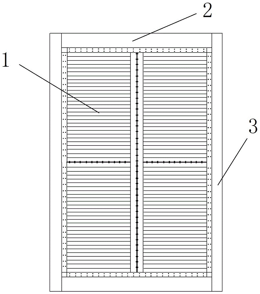
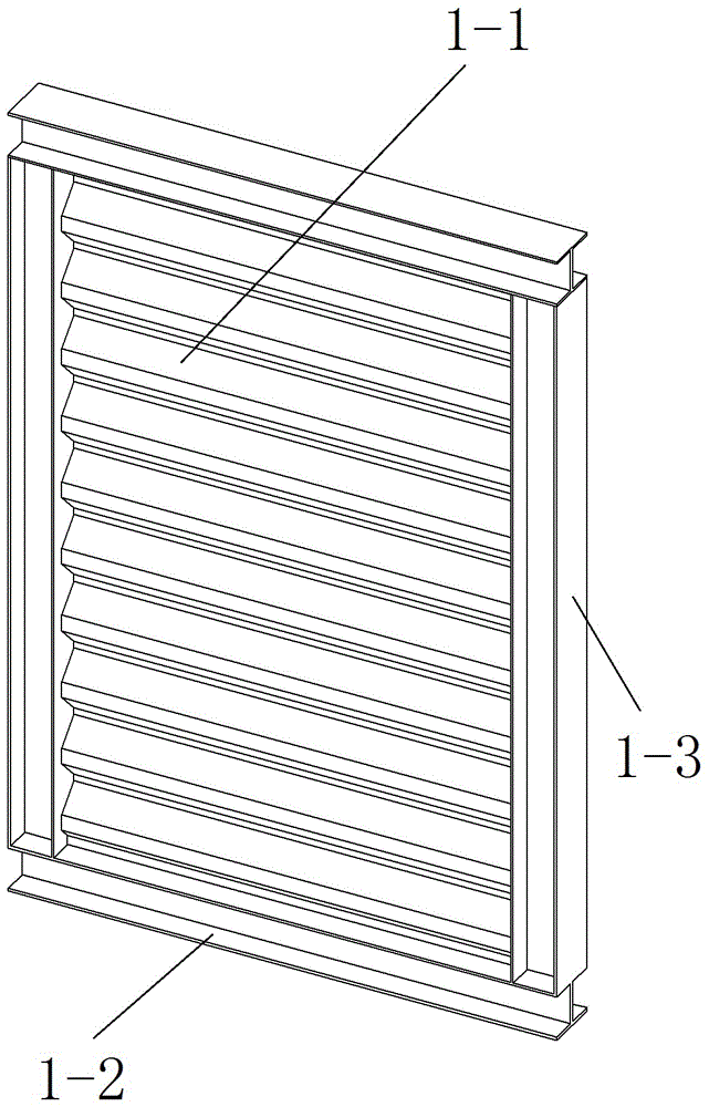
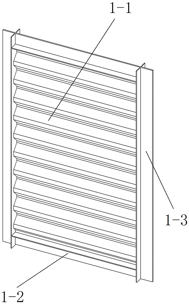
The invention discloses an assembled corrugated steel plate shear wall, which comprises one or a plurality of basic assembling units and an edge framework, wherein the basic assembling units are spliced through high-strength screw bolts and are connected with the edge framework; and each basic assembling unit is formed by transverse connecting elements, longitudinal connecting elements and corrugated web plates through welding. The assembled corrugated steel plate shear wall provided by the invention has the advantages that each basic assembling unit is formed by the corrugated web plates, so that the shear buckling load of a steel plate wall can be greatly improved; the use comfort of the steel plate shear wall structure is improved; the outer rigidity of the basic assembling unit surface of the assembled corrugated steel plate shear wall is great; and the transportation is convenient and fast. The lateral force resisting structure system of the assembled corrugated steel plate shear wall adopts field splicing by high-strength screw blots; the construction is convenient and fast; the quality is easy to guarantee; the assembled corrugated steel plate shear wall conforms to the industrial development trend of a building; and wide market application prospects are realized.

Description

technical field [0001] The invention belongs to the technical field of structural engineering, and relates to an assembled corrugated steel plate shear wall applied to multi-story steel structure residences or industrial workshops. Background technique [0002] The steel plate shear wall structure is a lateral force resistant structural system applied to multi-storey or high-rise buildings, which consists of embedded steel plates, vertical edge members (columns) and horizontal edge members (beams). [0003] The traditional flat steel plate wall is generally used as a lateral force-resistant member of a high-rise structure, and the cost is relatively expensive by using medium-thick steel plates or configuring stiffeners. Although the use of non-stiffened thin steel plate walls can reduce costs and have better economic benefits, its buckling load is very low, and it mainly relies on the tension bands after buckling of the steel plates to resist lateral forces; while the buckle...

Claims


Application Information

Patent Timeline
Patent Type & Authority Applications(China)
IPC IPC(8): E04B2/58
CPCE04B2/58
Inventor 刘晓刚郑云侯兆新逯鹏李贺贺龚超邱林波
Owner CENT RES INST OF BUILDING & CONSTR CO LTD MCC GRP
Why Eureka
Try Eureka