
Axial parallel clutch driving device based on radial-moving clutch pin

A technology of clutch transmission and clutch pin, which is applied in the field of mechanical transmission and can solve the problems of large separation and implicated torque of the expansion and tightening structure

Inactive Publication Date: 2016-07-06
王陈梓
View PDF1 Cites 0 Cited by
  • Summary
  • Abstract
  • Description
  • Claims
  • Application Information

AI Technical Summary

Problems solved by technology

In addition to the patents declared by the inventor himself, the clutch patent (02131503.5) filed by a foreigner in China in 2002 is relatively close to the present invention. This patent uses a leaf-shaped wide spring to eccentrically squeeze the rolling parts that can freely roll in the circumferential direction. In order to achieve the transmission purpose of expansion and driving, the disadvantage is that the separation and involvement torque of the expansion structure is relatively large, which is not suitable for the application environment that requires a small separation and involvement torque. This patent separates the structure through the action surface of the clutch pin and the rotary stop contact pair. The setting effectively overcomes this defect without affecting the clutch function

Method used


Image

  • Axial parallel clutch driving device based on radial-moving clutch pin
  • Axial parallel clutch driving device based on radial-moving clutch pin
  • Axial parallel clutch driving device based on radial-moving clutch pin

Examples


Embodiment Construction

[0017] Combine below figure 1 , 2 , 3, 4, 5 and 6 are further detailed descriptions of the embodiments of the patent of the present invention.

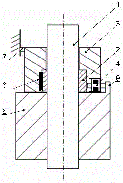
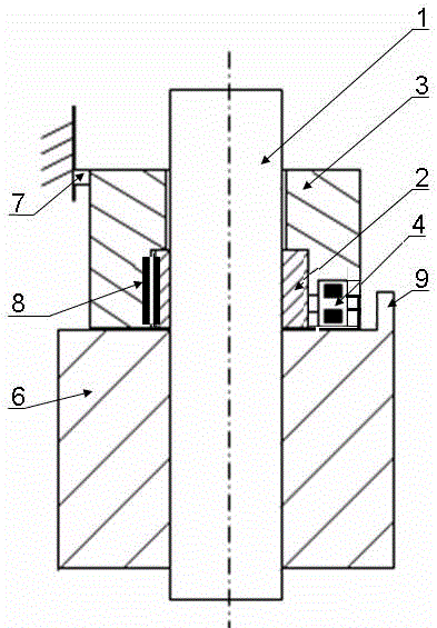
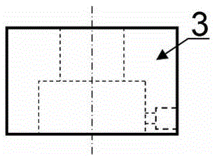
[0018] Embodiment of the present invention's axially parallel clutch transmission based on radially moving clutch pins: this clutch transmission consists of an active rotating part [1], a radially driving rotating part [2], a sleeve with a radial pin hole [3], clutch pin [4], magnet [5], driven rotating part [6] with a stop, sleeve rotating damping part [7], respectively located in the radial direction of the driving rotating part [2] and the belt diameter It is composed of the rotation stop contact pair [8] on the sleeve [3] of the pin hole, wherein, such as Image 6 As shown, when the driven rotating part [6] is processed, the convex edge in the circumferential direction is reserved as the stop [9], the clutch pin [4] is embedded with a magnet [5], and the radially driving rotating part [2] adopts Figure 5 The one on the left is...


PUM


Abstract

In the forward and reverse transmission, it is often necessary to realize the controllable clutch between the active rotating part and the driven rotating part. At present, electromagnetic clutch is mostly used, which requires additional auxiliary power to realize the clutch action. There is only one type of forward and reverse transmission based on radial A clutch transmission device that moves the clutch pin, but because the four components of the invention, the active rotating part, the radially driving rotating part, the sleeve with radial pin holes and the driven rotating part with pin pits, are coaxial from the inner circle To the outer circle setting, on the one hand, the overall diameter of the clutch is too large, the processing is complicated, the installation difficulty and the reliability are not ideal. The present invention adopts an axially parallel clutch structure based on radially moving clutch pins, and the sleeve with radial pin holes and the driven rotating member with stops are arranged side by side in the axial direction, effectively solving the above problems. It is a forward and reverse transmission clutch device with high cost performance and high reliability.

Description

technical field [0001] The patent of the present invention relates to an axially parallel clutch transmission device based on radially moving clutch pins, which belongs to the technical field of mechanical transmission. . Background technique [0002] In the forward and reverse mechanical transmission, it is often necessary to realize the controllable clutch between the active rotary part and the driven rotary part. At present, electromagnetic clutch and friction pair clutch are used more often. The former needs additional auxiliary power to realize the clutch action, and the latter often Wear and friction adjustment problems occur, and there is a lack of a simple automatic clutch device that utilizes the power of the active rotary part to complete the clutch and has a small separation torque. The inventor previously applied for a patent for a clutch transmission device (ZL2014200791605) based on radially moving clutch pins in forward and reverse transmission, but found in ...

Claims


Application Information

Patent Timeline
Patent Type & Authority Applications(China)
IPC IPC(8): F16D41/06F16D27/01
CPCF16D41/06F16D27/01
Inventor 王陈梓罗泉
Owner 王陈梓
Learn More