
A radio frequency test device and system

A radio frequency test system and radio frequency test technology, applied in the field of radio frequency, can solve the problems of inaccurate radio frequency performance testing of intelligent terminals, and achieve the effect of improving accuracy and improving production efficiency

Active Publication Date: 2018-09-21
GUANGDONG OPPO MOBILE TELECOMM CORP LTD
View PDF7 Cites 0 Cited by
  • Summary
  • Abstract
  • Description
  • Claims
  • Application Information

AI Technical Summary

Problems solved by technology

[0006] Embodiments of the present invention provide a radio frequency testing device and system, which can solve the technical problem of inaccurate radio frequency performance testing of intelligent terminals

Method used


Image

  • A radio frequency test device and system
  • A radio frequency test device and system
  • A radio frequency test device and system

Examples


Embodiment 1

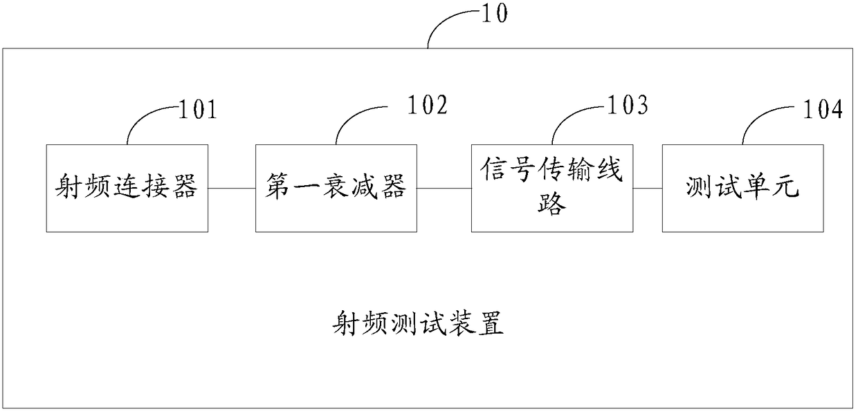
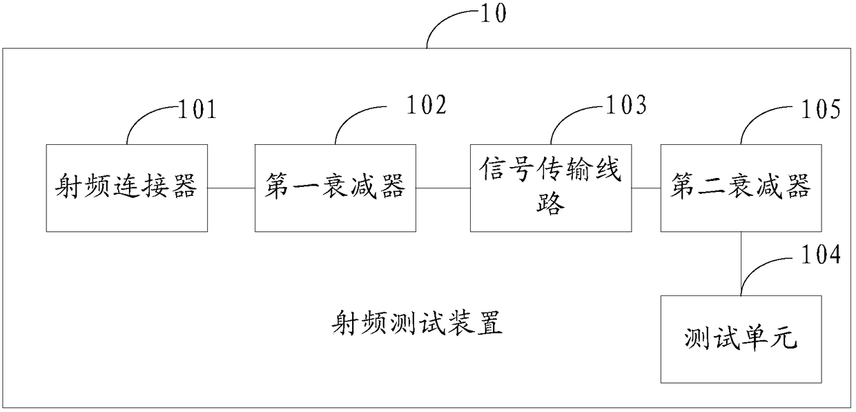
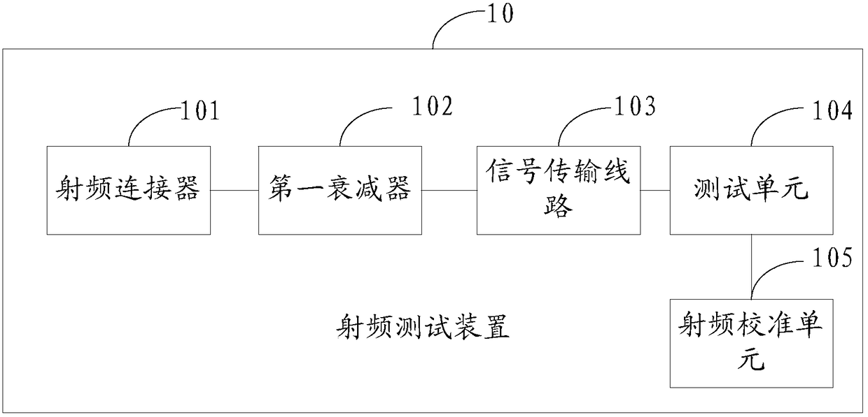
[0041] refer to figure 1 , figure 1 It is a schematic structural diagram of a radio frequency testing device provided by an embodiment of the present invention. The radio frequency testing device 10 includes: a radio frequency connector 101, a first attenuator 102, a signal transmission line 103 and a test unit 104, as follows:

[0042] A radio frequency connector 101, configured to receive a radio frequency signal sent by the mobile terminal, and transmit the radio frequency signal to the first attenuator 102;

[0043] The first attenuator 102 is used to transmit the radio frequency signal to the signal transmission line 103;

[0044] a signal transmission line 103, configured to transmit the radio frequency signal to the test unit 104;

[0045] The testing unit 104 is configured to test the radio frequency parameters of the mobile terminal according to the radio frequency signal, so as to obtain test results.

[0046] Wherein, the decibel number of the first attenuator 1...

Embodiment 2

[0058] Accordingly, refer to Figure 4 , the embodiment of the present invention provides a radio frequency test system, the radio frequency test system may include: a mobile terminal 20 and the radio frequency test device 10 described in the first embodiment;

[0059] Wherein, the radio frequency test device 10 includes: a radio frequency connector 101, a first attenuator 102, a signal transmission line 103 and a test unit 104, as follows:

[0060] a radio frequency connector 101, configured to receive a radio frequency signal sent by the mobile terminal 20, and transmit the radio frequency signal to the first attenuator 102;

[0061] The first attenuator 102 is used to transmit the radio frequency signal to the signal transmission line 103;

[0062] a signal transmission line 103, configured to transmit the radio frequency signal to the test unit 104;

[0063] The testing unit 104 is configured to test the radio frequency parameters of the mobile terminal according to the ...


PUM


Abstract

The invention discloses a radio frequency test device and a system. In the embodiment of the invention, a radio frequency connector is adopted to receive a radiofrequency signal transmitted by a mobile terminal, and the radio frequency signal is transmitted to a first attenuator; the first attenuator transmits the radiofrequency signal to a signal transmission circuit which transmits the radiofrequency signal to a test unit; the test unit performs testing on the radio frequency parameters of the mobile terminal according to the radiofrequency signal in order to obtain the test result; an attenuator is added between the radio frequency connector and the signal transmission circuit; the application of the attenuator can buffer the characteristic of impedance change, reduces the interference on the radio frequency connector impedance by the signal transmission circuit, and enables the impedance of the radio frequency connector to be consistent with the impedance of the intelligent terminal radio frequency system as much as possible. Compared with the prior art, the radio frequency test device and system can improve the accuracy of the intelligent terminal radio frequency performance test, and thus improve the production efficiency of the intelligent terminal.

Description

technical field [0001] The invention relates to the field of radio frequency technology, in particular to a radio frequency testing device and system. Background technique [0002] With the development of smart terminals, more and more functions are compatible with smart terminals, which not only enriches users' lives, but also brings convenience to users. [0003] As we all know, the radio frequency performance is an important performance of the smart terminal, which is related to the quality of the radio frequency communication of the smart terminal. Therefore, in order to ensure the radio frequency performance of the smart terminal or ensure the consistency of the radio The terminal performs a radio frequency calibration test. [0004] In order to ensure the accuracy of the RF calibration test, it is necessary to keep the impedance of the connection end of the calibration test system consistent with the impedance of the RF system of the smart terminal, that is, to ensure...

Claims


Application Information

Patent Timeline
Patent Type & Authority Patents(China)
IPC IPC(8): H04B17/00H04B17/391
CPCG01R31/00
Inventor 陈再成
Owner GUANGDONG OPPO MOBILE TELECOMM CORP LTD
Learn More