
Transmission line and terminal device

A transmission line and signal transmission line technology, applied in the direction of waveguide, circuit, waveguide-type devices, etc., can solve the problems of performance degradation, impedance mismatch, damage to transmission lines, etc., and achieve the effect of ensuring transmission performance, not easy to break, and easy to bend

Active Publication Date: 2020-07-17
AAC TECH PTE LTD
View PDF6 Cites 0 Cited by
  • Summary
  • Abstract
  • Description
  • Claims
  • Application Information

AI Technical Summary

Problems solved by technology

The space available for the layout of traditional RF coaxial transmission lines is getting smaller and smaller, so new transmission structures emerge as the times require; for the design of multi-antenna RF transmission lines, PCB planar circuits or flexible circuits are mainly used for design, and the commonly used structures are mainly micro Stripline, coplanar waveguide, stripline and dielectric integrated waveguide, etc.; integrated terminal equipment space structure, the general transmission line module needs to be bent once or more, and there is a risk of fracture in the narrow bending area, so local or Gridded copper design over large areas; gridded copper structures can disrupt the transmission line reference ground structure, causing impedance mismatches that result in degraded performance

Method used


Image

  • Transmission line and terminal device
  • Transmission line and terminal device
  • Transmission line and terminal device

Examples


Embodiment Construction

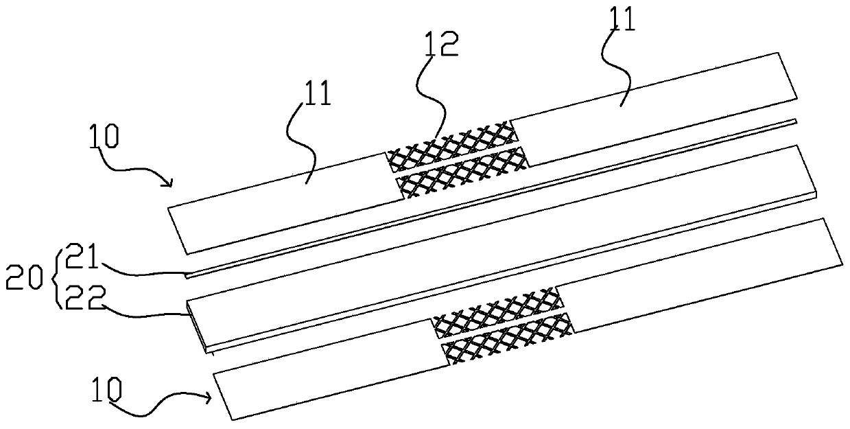
[0016] In order to make the objectives, technical solutions and advantages of the embodiments of the present invention clearer, various embodiments of the present invention will be described in detail below in conjunction with the accompanying drawings. However, those of ordinary skill in the art can understand that in each implementation manner of the present invention, many technical details are provided for readers to better understand the present invention. However, even without these technical details and various changes and modifications based on the following implementation modes, the technical solution claimed in the present invention can also be realized.

[0017] Embodiments of the present invention provide a transmission line and a terminal device. When an antenna is arranged in a terminal device, it is necessary to electrically connect the antenna and a signal processing unit of the terminal device through a transmission line. In this regard, through this transmiss...


PUM


Abstract

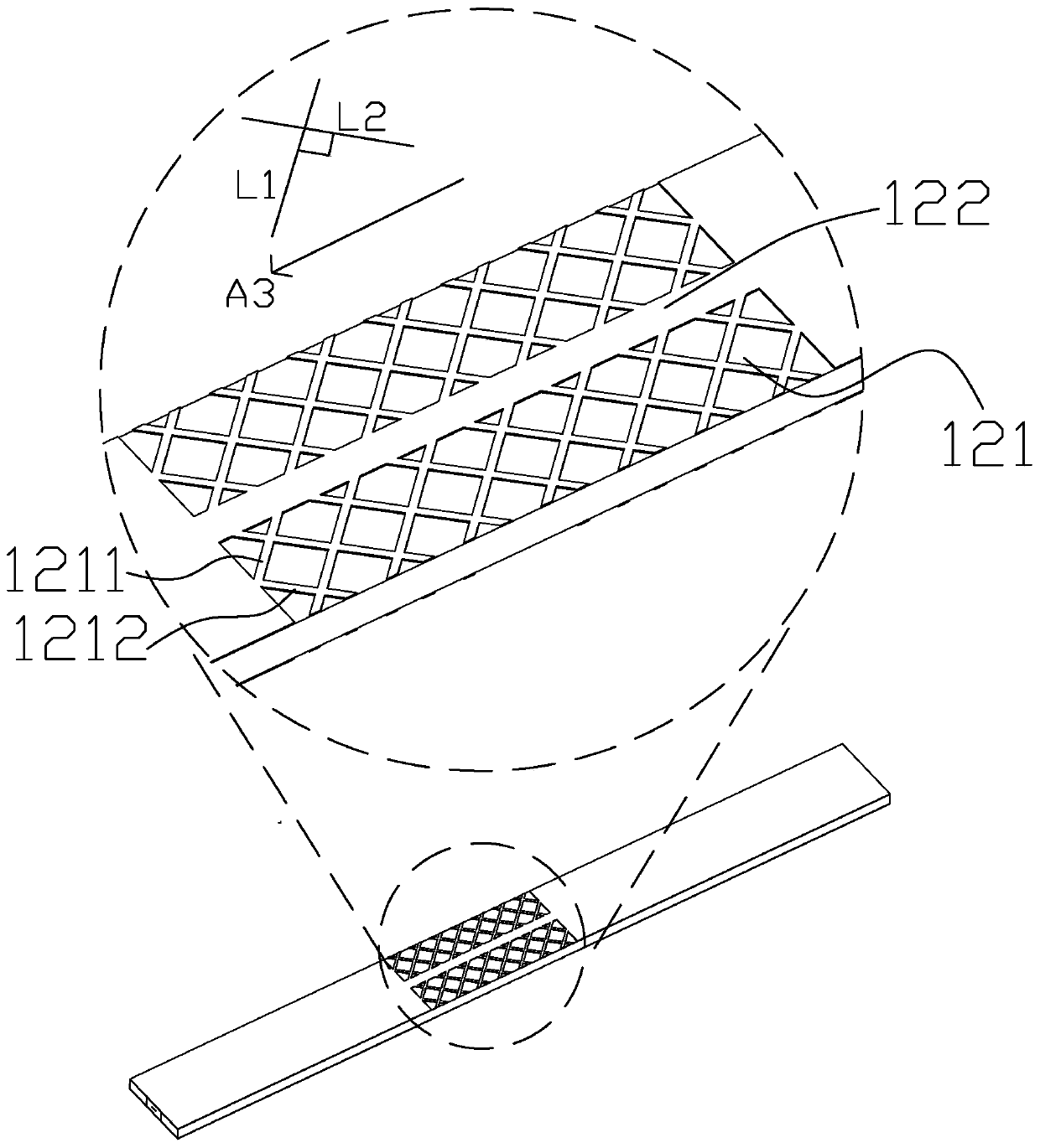
The invention provides a transmission line. The transmission line comprises at least one layer of grounding conductor and a signal layer, a signal transmission line is arranged in the signal layer, and the width of the grounding conductor is greater than that of the signal transmission line. The transmission line comprises at least two connecting areas and at least one bending area clamped betweenthe two connecting areas in the signal transmission direction. In the bending area, the grounding conductor comprises a grounding piece corresponding to the signal transmission line and grounding grids arranged at the two sides of the grounding piece in the direction perpendicular to the signal transmission direction, and the grounding piece and the grounding grids are both connected with the grounding conductors of the connecting areas at the two ends of the grounding piece and the grounding grids. According to the transmission line and the terminal device provided by the invention, the meshstructure is arranged in the bending area of the grounding conductor, so that the transmission line is easy to bend during wiring, and the grounding sheets are arranged at the projection positions ofthe signal transmission line on the grounding conductor in the bending area, so that the influence of the mesh structure on the impedance is reduced, and the transmission performance of the transmission line is ensured.

Description

【Technical field】 [0001] The invention relates to the field of signal transmission control, in particular to a transmission line and terminal equipment. 【Background technique】 [0002] With the development of 5G (5th generation mobile networks) and consumer electronics technology, research on multi-antenna technology has a long history. The space available for the layout of traditional RF coaxial transmission lines is getting smaller and smaller, so new transmission structures emerge as the times require; for the design of multi-antenna RF transmission lines, PCB planar circuits or flexible circuits are mainly used for design, and the commonly used structures are mainly micro Stripline, coplanar waveguide, stripline and dielectric integrated waveguide, etc.; integrated terminal equipment space structure, the general transmission line module needs to be bent once or more, and there is a risk of fracture in the narrow bending area, so local or Mesh copper design over large ar...

Claims


Application Information

Patent Timeline
IPC IPC(8): H01P3/08
CPCH01P3/081
Inventor 詹大伟陈勇利何家勇
Owner AAC TECH PTE LTD
Learn More