
Target object tracking method and device

A target object, object technology, applied in the field of image processing

Inactive Publication Date: 2016-07-06
RICOH KK
View PDF6 Cites 6 Cited by
  • Summary
  • Abstract
  • Description
  • Claims
  • Application Information

AI Technical Summary

Problems solved by technology

This technology uses the whole body and head to detect pedestrians, so it is not suitable for the situation where the whole body and head are not clear but other parts are clear

Method used


Image

  • Target object tracking method and device
  • Target object tracking method and device
  • Target object tracking method and device

Examples


no. 1 example

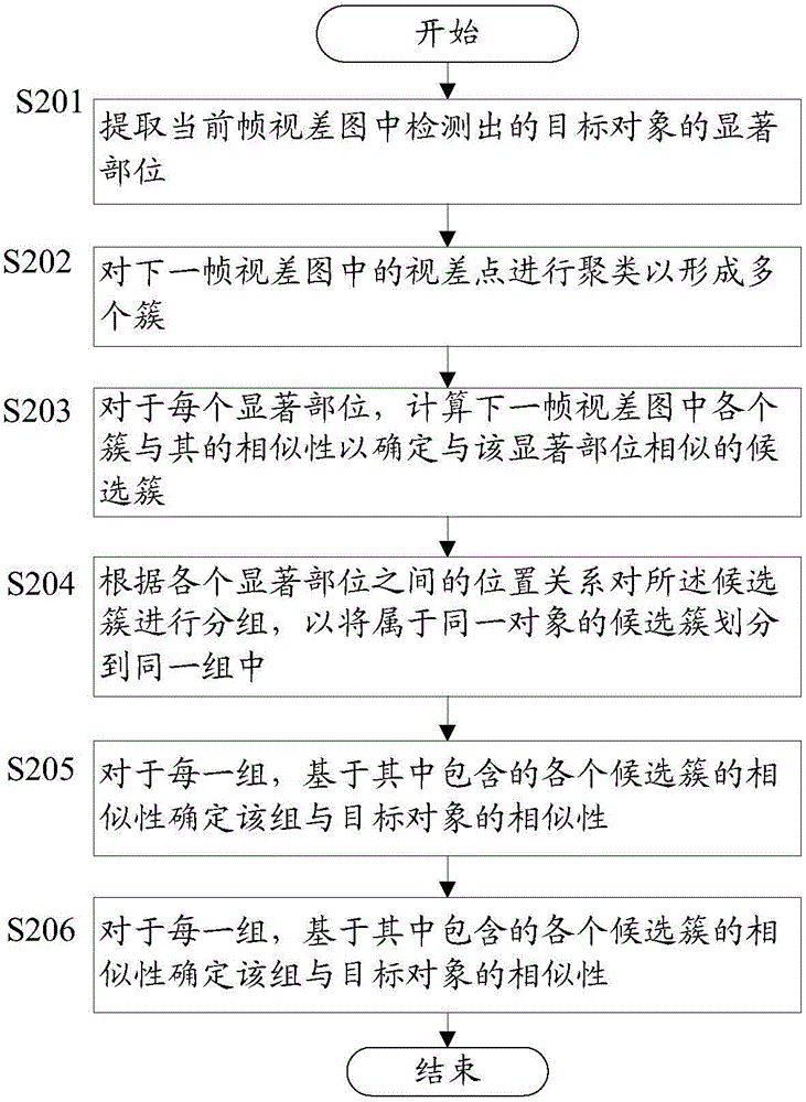
[0026] figure 2 A flow chart of the target object tracking method according to the first embodiment of the present invention is shown.

[0027] Such as figure 2 As shown, in step S201, the salient parts of the target object detected in the disparity map of the current frame (frame N) are extracted.

[0028] As mentioned above, each pixel in the disparity map represents a disparity value, which can be obtained through a stereo matching method. However, for some pixels whose disparity values ​​cannot be calculated through stereo matching, these pixels are points without disparity values. According to the principle of stereo matching, it can be known that the disparity value can usually be calculated for the pixels located on the edge of the object whose gray scale changes. Therefore, for the pixels on the edge where the gray level changes, there is usually a parallax value. For example, Figure 3(a) and 3(b) The schematic diagrams respectively illustrate the grayscale im...

no. 2 example

[0078] The target object detection method according to this embodiment is basically the same as the method in the first embodiment, the only difference is that the target object detection method according to this embodiment further includes: determining each salient part of the target object in the disparity map of the current frame Significance; assign weight values ​​to each of the prominent parts, so that the weight value of the prominent part with higher significance is greater, and then in step S205' corresponding to step S205 in the first embodiment, for each When a group determines its similarity with the target object, calculate the weighted sum of the similarities of each candidate cluster contained in the group as the similarity between the group and the target object, wherein the weight value of each candidate cluster is the same as the candidate cluster The weight value of similar salient parts. These differences are described below.

[0079] The saliency of each ...


PUM


Abstract

The invention provides a target object tracking method and device. The method comprises the steps: extracting marked parts of a target object detected in a current frame parallax image; carrying out the clustering of parallax points in a next frame parallax image, so as to form a plurality of cluster; calculating the similarity of each cluster in the next frame parallax image with each marked part, so as to determined candidate clusters similar to the marked parts; carrying out the grouping of all candidate clusters according to the position relation among all marked parts, so as to enable the candidate clusters belonging to the same object to be divided into the same group; determining the similarity of each group with the target object based on the similarity of all candidate clusters in each group; selecting the group with the highest similarity, and enabling the position where the group is located to serve as the position where the target object is located in the next frame parallax image. Through the technology of target object tracking, the method also can obtain an accurate tracking result under the conditions that the posture of the target object is frequency changed and the target object is partly shaded.

Description

technical field [0001] The present invention generally relates to image processing, and in particular to a target object tracking method and device Background technique [0002] Object tracking technology has a wide range of applications in many fields such as object positioning, video surveillance, robot navigation, assisted driving, and driving warning. At present, object tracking technology still has problems in some scenarios, such as misidentifying the object being tracked as a new object, misidentifying the object being tracked as another object, and losing the tracked object. Especially in pedestrian tracking, this problem is especially serious due to the constantly changing poses of pedestrians, the large number of pedestrians, and the frequent occurrence of occlusion problems. [0003] US patent application US20120194680 discloses a technology for detecting pedestrians by matching detected images with pre-stored human outline templates. In this application, the en...

Claims


Application Information

Patent Timeline
Patent Type & Authority Applications(China)
IPC IPC(8): G06T7/20G06V10/762
CPCG06V40/23G06V40/103G06V20/58G06V10/267G06V10/762G06F18/23
Inventor 游赣梅刘殿超杨田雨鲁耀杰师忠超
Owner RICOH KK
Learn More