Substrate Processing Apparatus

A plasma and processing device technology, applied in the field of substrate processing devices, can solve the problems of deposits, nozzle consumption, etc., and achieve the effect of eliminating potential difference and suppressing the generation of electric field

Inactive Publication Date: 2016-07-06
TOKYO ELECTRON LTD
View PDF4 Cites 1 Cited by
  • Summary
  • Abstract
  • Description
  • Claims
  • Application Information

AI Technical Summary

Problems solved by technology

There is a problem that the wall surface of the chamber 101 and the shower head 103 are consumed by the plasma generated in the upper space US, and deposits are generated.

Method used


Image

  • Substrate Processing Apparatus
  • Substrate Processing Apparatus
  • Substrate Processing Apparatus

Examples


Embodiment Construction

[0034] Hereinafter, embodiments of the present invention will be described in detail with reference to the accompanying drawings.

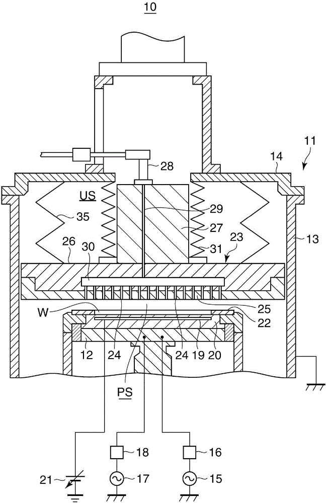
[0035] figure 1 It is a cross-sectional view schematically showing the structure of the substrate processing apparatus according to the embodiment of the present invention. This substrate processing apparatus is configured to perform dry etching processing on a wafer.

[0036] exist figure 1 Among them, the substrate processing apparatus 10 has a cylindrical chamber 11 (cylindrical container) for accommodating, for example, a wafer W having a diameter of 300 mm. The disc-shaped susceptor 12 (counter electrode) of the wafer W. The chamber 11 has a cylindrical side wall 13 and a disk-shaped cover 14 (one end wall of the cylindrical container) covering the upper end portion of the side wall 13 in the drawing.

[0037] The inside of the chamber 11 is decompressed by TMP (TurboMolePump, turbo molecular pump) and DP (DryPump, dry pump) (both of wh...


PUM


Abstract

Disclosed is a substrate processing apparatus capable of suppressing generation of plasma in the space between a moving electrode and an end wall at one side of a cylindrical chamber. The substrate processing apparatus includes a cylindrical chamber to receive a wafer, a shower head movable along a central axis of the chamber inside the chamber, a susceptor opposing the shower head in the chamber, and a flexible bellows connecting the shower head to a cover of the chamber, wherein a high frequency power is applied to a processing space presented between the shower head and the susceptor, processing gas is introduced into the processing space, the shower head and the side wall of the chamber are non-contact to each other, and a bypass member is installed electrically connecting the shower head and the cover or the side wall of the chamber.

Description

[0001] (This application is a divisional application of the application whose filing date is March 23, 2011, the application number is 201110076088.1, and the invention name is "substrate processing device".) technical field [0002] The present invention relates to a substrate processing apparatus, and more particularly, to a substrate processing apparatus having an electrode that can move within a processing chamber. Background technique [0003] A substrate processing apparatus for performing plasma processing on a semiconductor wafer as a substrate (hereinafter simply referred to as a "wafer") includes a chamber for accommodating the wafer and capable of depressurizing the inside, and a lower portion disposed inside the chamber The mounting table (hereinafter referred to as "susceptor") of the chamber and the shower head arranged opposite to the susceptor inside the chamber. The susceptor is used to mount the wafer and functions as an electrode that is connected to a hig...

Claims


Application Information

Patent Timeline
Patent Type & Authority Applications(China)
IPC IPC(8): H01J37/32
CPCH01J37/32091H01J37/32568
Inventor 吉村章弘佐藤彻治堀口将人和田畅弘小林真辻本宏田村纯直井护
Owner TOKYO ELECTRON LTD
Why Eureka
Try Eureka