Connector and connector device

a technology of connectors and connectors, applied in the direction of coupling devices, coupling contact members, coupling devices, etc., can solve the problems of electromagnetic interference, impede the fulfillment of the requirement for high-frequency characteristics,

Active Publication Date: 2021-03-16
HIROSE ELECTRIC GROUP
View PDF12 Cites 2 Cited by
  • Summary
  • Abstract
  • Description
  • Claims
  • Application Information

AI Technical Summary

Benefits of technology

[0045]In the present connector device and the present connector, when the connectors are mated together, the shield for electromagnetically shielding the terminals of the plug connector and the shield for electromagnetically shielding the terminals of the receptacle connector are in contact with each other and are electrically connected by the shield mating portions provided at the ends in the longer direction of each housing. Thus, it is possible to eliminate substantially the potential difference between the shields. As a result, a sufficient electromagnetic shield function can be obtained. In addition, with the present connector device and the present connector having such configuration, it is possible to avoid the inner / outer dual structure of the shields that impedes downsizing of the connector. Thus, it is possible to reduce the areas occupied by the connectors on the substrates. As a result, the present connector device and the present connector contribute to achieving high density mounting.

Problems solved by technology

One of the causes that impede the fulfillment of the requirement for the high-frequency characteristics is the so-called electromagnetic interference (EMI) due to, e.g., electromagnetic-wave noise signals generated from the connector terminals.

Method used


Image

  • Connector and connector device
  • Connector and connector device
  • Connector and connector device

Examples


first embodiment

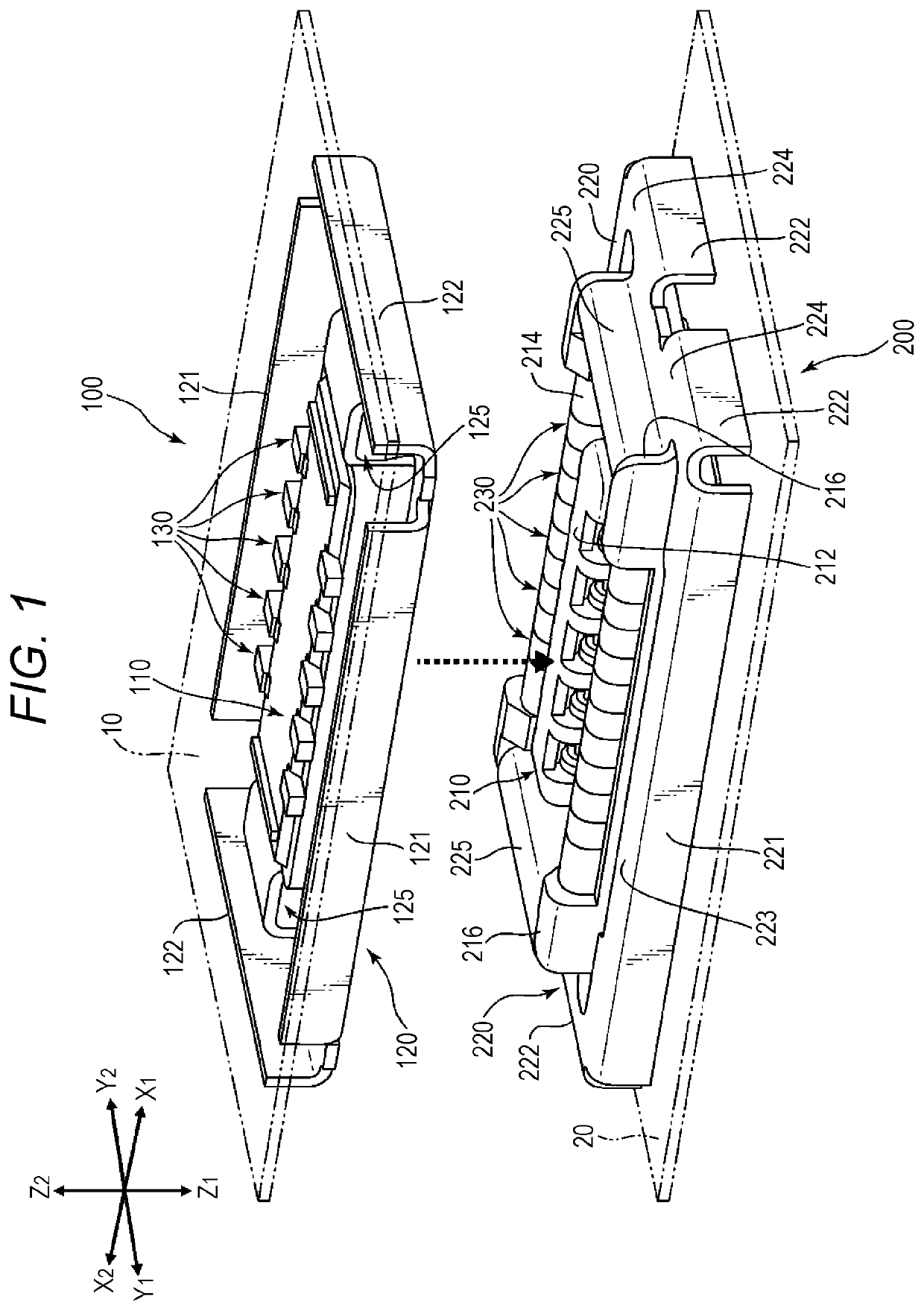
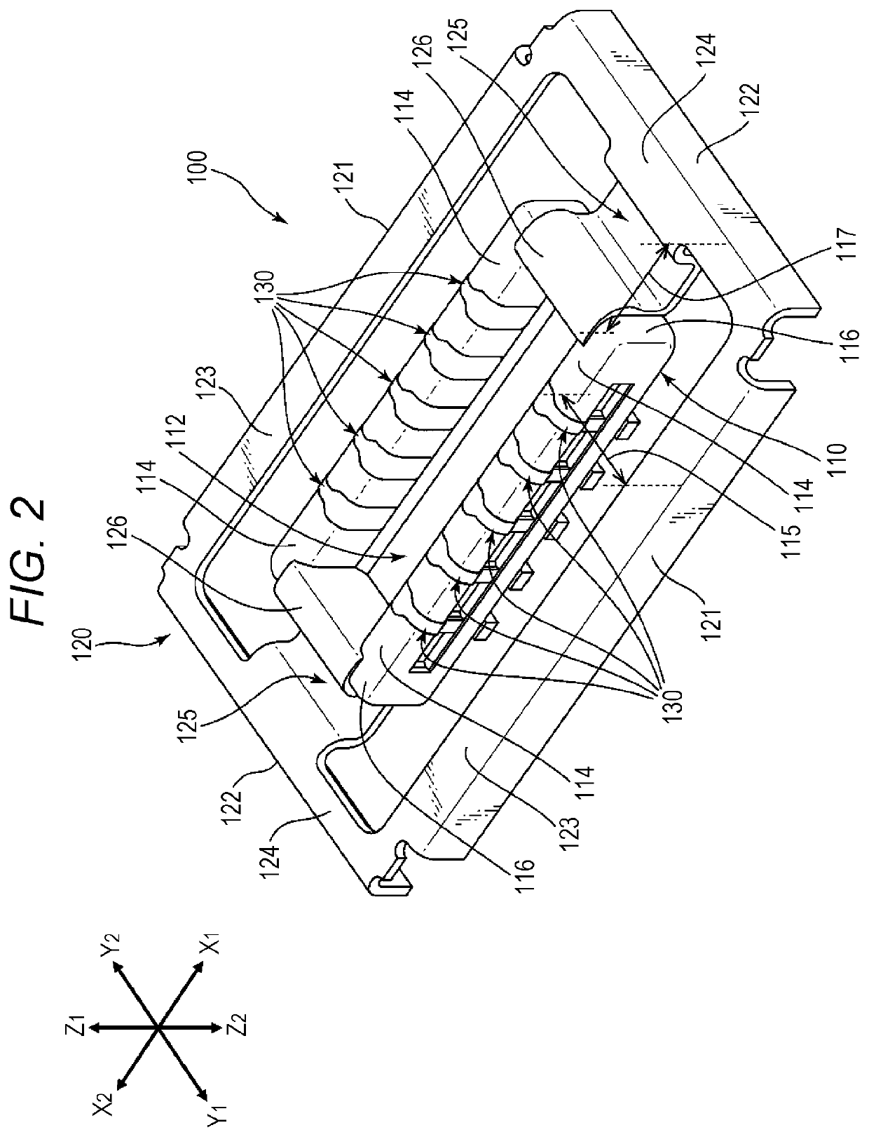
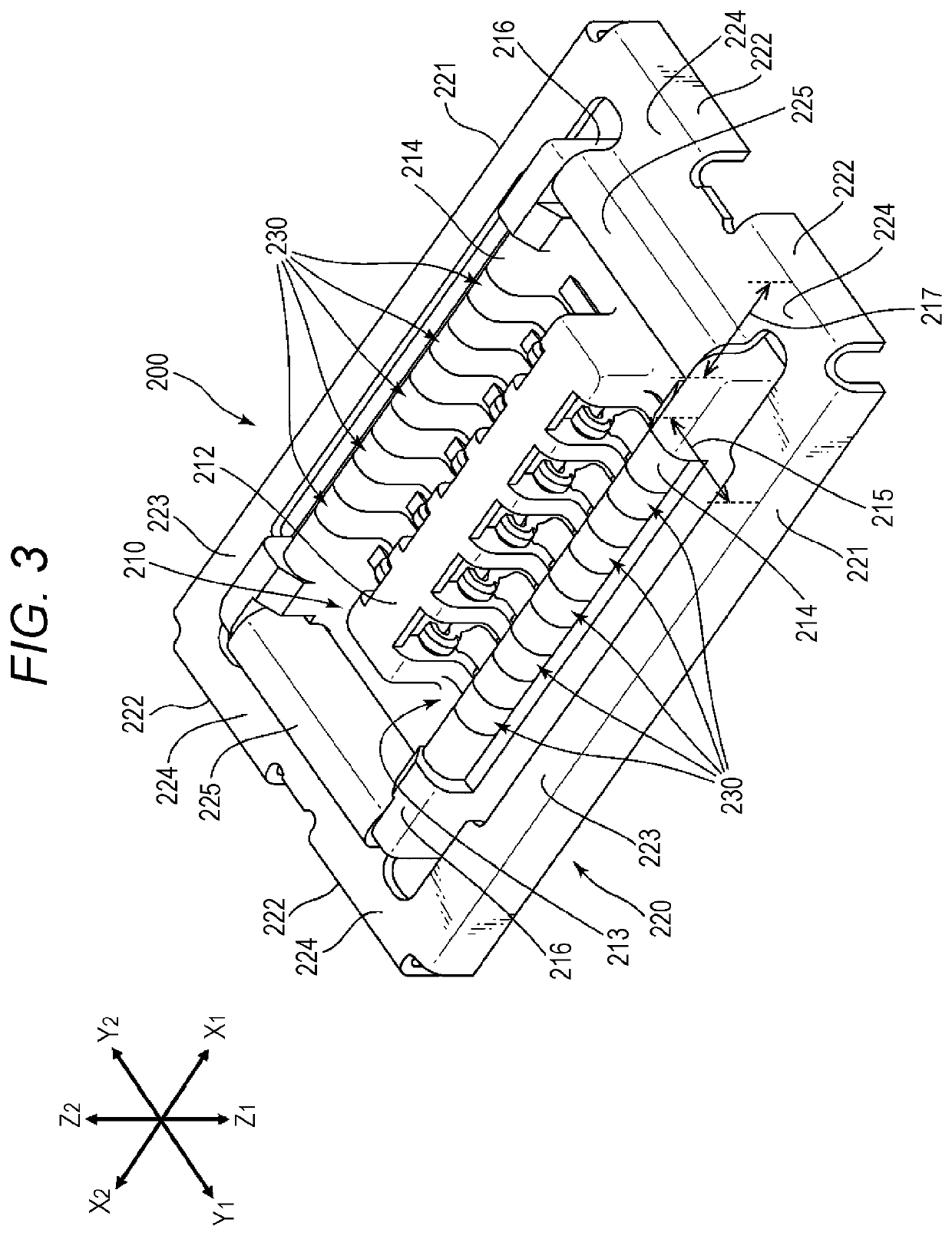
[0047]FIG. 1 illustrates a connector device according to the present disclosure. The connector mating direction is the Z1-Z2 direction (Z-axis direction) as shown. A plug connector 100 is mated with a receptacle connector 200, which is on the Z1-side in the Z-axis direction of the counterpart connector. The receptacle connector 200 is mated with the plug connector 100, which is the counterpart connector on the Z2-side in the Z-axis direction. In the present embodiment, the longer direction corresponds to the X1-X2 direction (X-axis direction), and the shorter direction corresponds to the Y1-Y2 direction (Y-axis direction). In FIG. 1, some of a plurality of terminals of each of the plug connector 100 and the receptacle connector 200 are designated with sign “130” or “230”, and designation of the other terminals with an identical shape is omitted. This similarly applies to the other drawing figures.

[0048]The connector device illustrated in FIG. 1 includes the plug connector 100 and th...

second embodiment

[0093]In the second embodiment illustrated in FIG. 5 and FIG. 6, the plug shield cutouts 326 are provided in the plug connector 300, and the receptacle shield protrusions 426 are provided in the receptacle connector 400. However, this is not a limitation, and the shield cutouts may be provided in the receptacle connector, and the shield protrusions may be provided in the plug connector. In the following embodiments, it is also possible to exchange the configuration of the plug connector and the configuration of the receptacle connector.

[0094]FIG. 7 illustrates a connector device according to a third embodiment of the present disclosure. FIG. 8 illustrates the state in which the plug connector and the receptacle connector illustrated in FIG. 7 are mated together. The connector device illustrated in FIG. 7 and FIG. 8 includes a plug connector 500 and a receptacle connector 600. The basic configurations of the plug connector 500 and the receptacle connector 600 are similar to the basic...

third embodiment

[0095]The plug connector 500 is provided with a plurality of plug terminals 130, a plug housing 510 holding the plurality of plug terminals 130, and a plug shell 520 held on the plug housing 510. The basic configuration of the plug housing 510 is the same as that of the plug housing 310 for example.

[0096]The plug housing 510 of the plug connector 500 is insert-molded (integrally molded) with the plurality of identically shaped plug terminals 130, and is capable of holding the plurality of plug terminals 130. The plurality of plug terminals 130 is arranged at equal intervals in the longer direction (X-axis direction) in two rows. The plug shell 520, which is the outer conductor, has plate-shaped first plug shields 521 extending along the longer direction (X-axis direction) of the plug housing 510, and shield connecting portions 525 extending along second side walls 516 in the shorter direction (Y-axis direction) of the plug housing 510. The plug shell 520 is provided with the first ...


PUM


Abstract

A connector device including: a plug connector provided with a plurality of plug terminals, a plug housing holding the plurality of plug terminals along a longer direction, and a plug shell held on the plug housing; and a receptacle connector provided with a plurality of receptacle terminals, a receptacle housing holding the plurality of receptacle terminals along the longer direction, and a receptacle shell held on the receptacle housing. The plug shell and the receptacle shell are electrically connected in a state in which the plug connector and the receptacle connector are mated together.

Description

CROSS-REFERENCE TO RELATED APPLICATION[0001]This application claims priority from Japanese Patent Application No. 2019-000763 filed with the Japan Patent Office on Jan. 7, 2019, the entire content of which is hereby incorporated by reference.BACKGROUND ART1. Technical Field[0002]Aspects of the present disclosure relate to a connector and a connector device.2. Related Art[0003]In an example, a connector device includes a rectangular housing, and a plug-side connector (plug connector) and a receptacle-side connector (receptacle connector) for connecting substrates. In the housing, a plurality of terminals is arranged in two rows in the longer direction by insert molding (integral molding), for example. Such connector device is disclosed in JP-A-2017-033909, for example.[0004]The plug connector and the receptacle connector may be provided on a printed wiring board, a flexible flat cable and the like. For example, it is possible to connect substrates by mating together a receptacle conn...

Claims


Application Information

Patent Timeline
Patent Type & Authority Patents(United States)
IPC IPC(8): H01R13/6583H01R24/62H01R13/6591H01R107/00
CPCH01R13/6583H01R13/6591H01R24/62H01R2107/00H01R13/6581H01R12/707H01R12/716H01R13/6582H01R13/6594H01R13/24H01R12/73H01R13/20H01R25/006H01R13/629
Inventor SUNAGA, SHIRO
Owner HIROSE ELECTRIC GROUP
Why Eureka
Try Eureka